circuit-fantasia > circuit stories > building circuits > sensor bridge
Building Circuits on the Whiteboard
Sensor Bridge with Current Bias
< prev step - 0 - 1 - 2 - 3 - 4 - 5 - 6 - 7 - next step >
Starting point. "When biasing a sensor bridge, you've got two choices - voltage or current. A voltage reference driving the bridge typically provides you with a useful sensor signal. The other choice is to drive the bridge with a constant current source. As we'll see, a simple opamp current-source does the trick of reducing the problems of remote sensing. Also, current sources are not just for remote sensing. Some sensors (like RTD's) are recommended to be driven from a current source... (after eCircuitCenter)"
Well, let's prove this speculation on the whiteboard...
< prev step 0 - 1 - 2 - 3 - 4 - 5 - 6 - 7 next step >
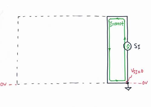
Let's start with placing a constant current source SI at the beginning of the line. It likes to be short connected; well, let's short it. Voltage drop VSI across the current source is zero as there is nothing to overcome.
< prev step - 0 - 1 - 2 - 3 - 4 - 5 - 6 - 7 - next step >
If we stretch the line to the desired place, disturbing resistances RS1 and RS2 appear. The current source reacts to this intervention by increasing its voltage VSI = VRS1 + VRS4; disturbing voltage drops VRS1 and VRS4 appear on the line resistances RS1 and RS4. As a result, the current I = VSI/(RS1 + VS4) remains unchanged.
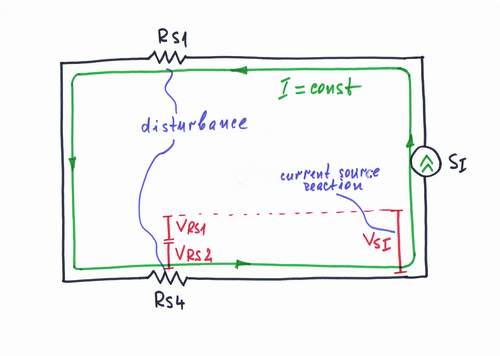
An experiment: Vary the line length. Imagine how the voltage bars vary when you lengthen or shorten the line. Does the current loop change its thickness? See this paper to know more about voltage bars and current loops.
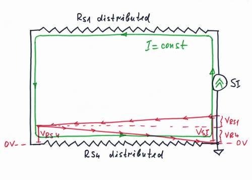
Actually, the resistances RS1 and RS4 are even distributed along the line. If you would like to be more precisely, you may imagine the voltage distribution along the line - this is the so-called voltage diagram, see also Class 3 and the paper).
< prev step - 0 - 1 - 2 - 3 - 4 - 5 - 6 - 7 - next step >
At the end of the line, we break the loop and connect a resistive sensor RS acting as a resistance-to-voltage converter. The current source reacts to the new intervention by increasing more its voltage VSI = VRS1 + VRS + VRS4. A voltage drop VRS appears on the resistor RS; it will act as a voltage output VOUT proportional to the input resistive quantity RS (temperature, movement etc.)
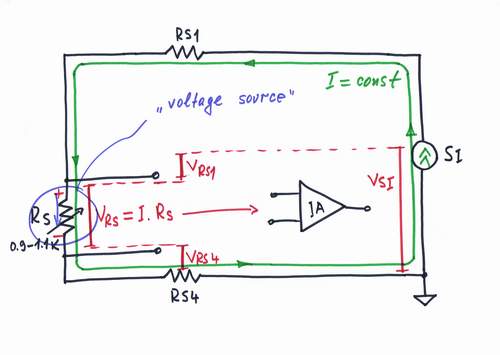
Only, VRS is a "floating" voltage; so, we have to convert it to a single-ended one by using a differential amplifier.
< prev step - 0 - 1 - 2 - 3 - 4 - 5 - 6 - 7 - next step >
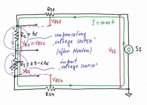
We usually want to obtain zero voltage VOUT = VRS0 = 0 at the nominal value of the sensor resistance RS0. Obviously, we have to subtract a compensating voltage VC = VRS0 from VRS. Only, remember that VRS is a "floating" voltage. Of course, we may subtract the voltages after the differential amplifier by using another subtractor but let's look for simpler solution.
We may create a compensating voltage just following the Norton's idea. That means to put another compensating resistor RC = RS0 connected in series with RS into the current loop. The resistor RC acts here as a current-to-voltage converter. The current source, performing accurately its "mission", reacts to the new intervention as usual - by increasing still more its voltage VSI = VRS4 + VRS + VRC + VRS.
An experiment: Imagine how the voltage bars vary when you decrease or increase the sensor resistance. Does the current loop change its thickness?
A question: What about the supply voltage of the current source?
< prev step - 0 - 1 - 2 - 3 - 4 - 5 - 6 - 7 - next step >
Now, we have to subtract voltages, in order to obtain the output voltage VOUT = VRS - VRC. For this purpose, we need a subtractor (or a summer acting as a subtractor).
The simple series summer (built according to II Ohm's law) doesn't help us since the input voltages are connected in one and the same direction (+ -, + -) along the line. So, we will get their sum instead the difference. We will use this arrangement later, in order to build a constant current source.
Then let's use the other possible summing circuit - the parallel resistive summer (built according to I Ohm's law). This simple circuit consists only of two resistors R3 and R4.
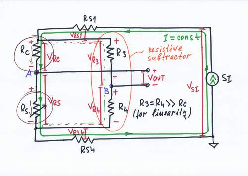
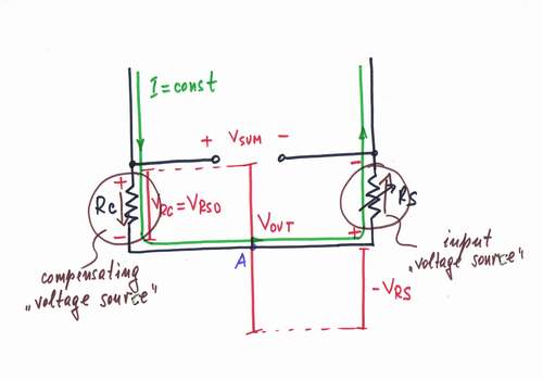
Now the input voltages VRS and VRC have an opposite polarity (referred to the middle point A between the resistors RS and RC); the voltage VB of the other middle point B between the resistors R1 and R2 (referred again to the middle point A) is the difference desired between the two input voltages. The output voltage VOUT = VAB is floating; so, we need again a differential amplifier.
If you wonder how this bare resistive circuit subtracts the input voltages, look at the voltage diagram below .
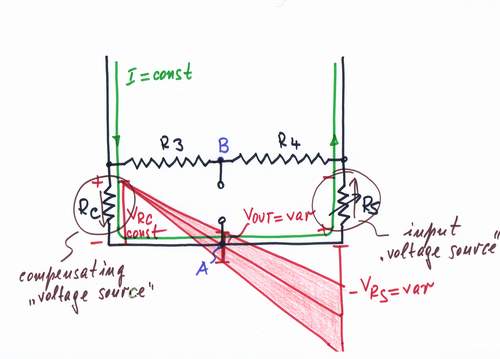
A question: What is the relation between the values of VRC, VRS, R3 and R4?
An important consideration: We want RS to act as a perfect current-to-voltage converter. So, in order not to affect the current flowing through the sensor, the resistors R3 and R4 have to have high resistance (e.g. R3 = R4 = 100k); otherwise, they will shunt the sensor. What do you think about this speculation? Check it!
< prev step - 0 - 1 - 2 - 3 - 4 - 5 - 6 - 7 - next step >
It is time to build the constant current source. There are a few tricks to keep a steady current; here we will apply the powerful negative feedback principle.
Every negative feedback system consists at least of three components: a power source E, a regulating element R and a comparator C.
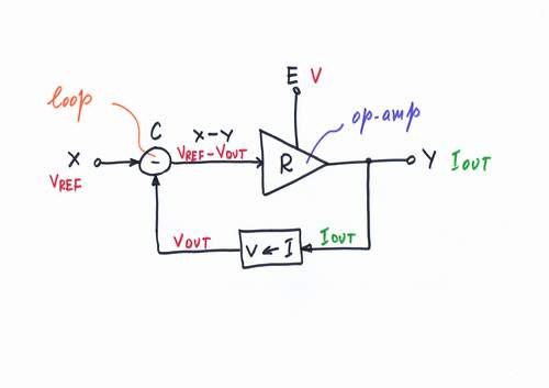
For some reasons (what?) we prefer voltage than current. So, let's get a voltage source as a power supply, an op-amp as a regulating element and the simplest series summer, acting as a subtractor - do you remember?
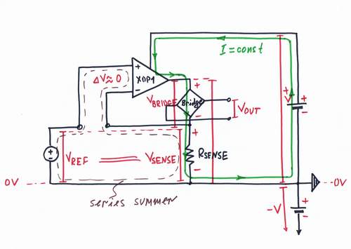
An experiment 1: Imagine how the voltage bars change their length and how the current loop changes its thickness when you vary the reference voltage VREF. What happens when VXOP1 reaches the positive rail +V?
An experiment 2: Imagine how the voltage bars and the current loop change when you vary the resistance RSENSE.
< prev step - 0 - 1 - 2 - 3 - 4 - 5 - 6 - 7 - next step >
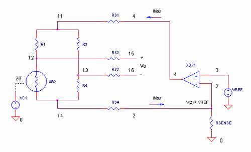
Finally, let's build the whole circuit. Note, that all the voltages are positive in this circuit.
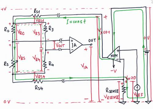
A question: May we supply the circuit using only the positive voltage +V?
An experiment: Imagine how all the voltage bars change their length and how the current loops change their thickness when you vary the sensor resistance.