circuit-fantasia > circuit stories > building circuits > op-amp ammeter short
 Circuit Stories on the Whiteboard...
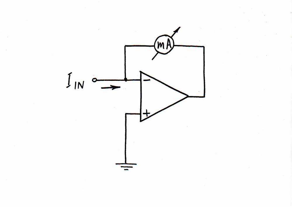
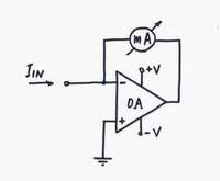
How do We Build an Op-amp Ammeter?
(How to convert the imperfect ammeter into an almost ideal op-amp ammeter...)
< prev step - 0 - 1 - 2 - 3 - 4 - 5 - 6 - next step >
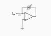
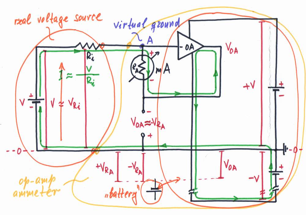
Classic explanations. "In this op-amp circuit, an imperfect ammeter (meter movement) is connected in the negative feedback loop. As the op-amp inputs draw no current, all the input current flows through the meter coil. The op-amp strives to make the voltage difference between the two inputs zero. Since V+ is grounded, this means that V- also will be zero (at virtual ground). As a result, the op-amp ammeter has zero input resistance..."
But yet, what is the basic idea behind this circuit? In order to reveal the truth, let's build the circuit on the whiteboard (convert the imperfect ammeter into an almost ideal op-amp one)...
< prev step - 0 - 1 - 2 - 3 - 4 - 5 - 6 - next step >
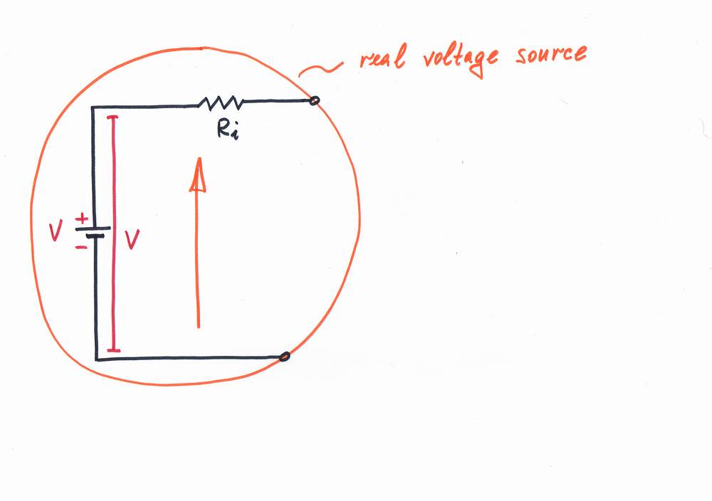
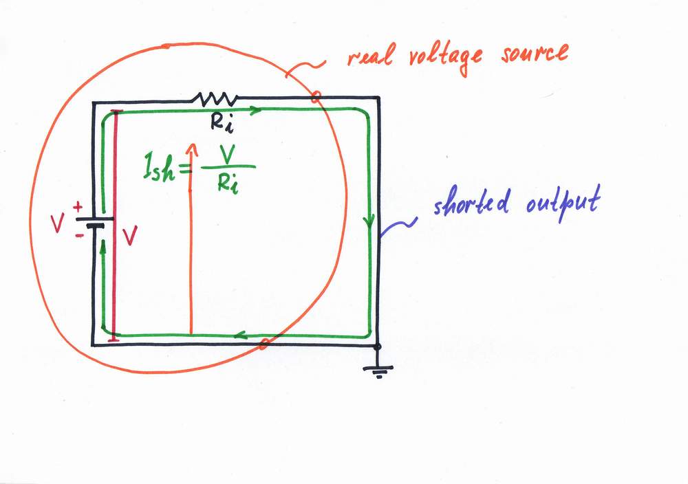
Imagine we have a real voltage source with a voltage V and an internal resistance Ri.
< prev step - 0 - 1 - 2 - 3 - 4 - 5 - 6 - next step >
Then suppose that we have to measure the current Ish = V/Ri that flows if you short the real voltage source.
Building op-amp ammeter (go to Step 1)
< prev step - 0 - 1 - 2 - 3 - 4 - 5 - 6 - next step >
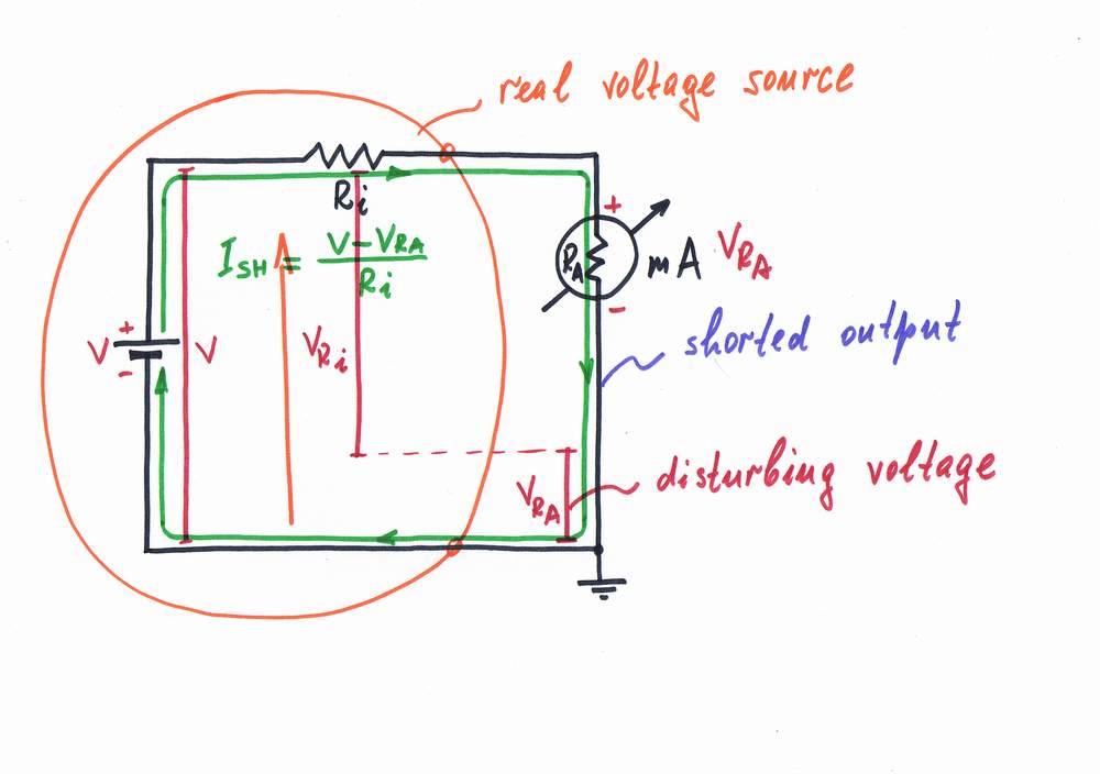
Problem. For this purpose, we break the circuit and connect an ammeter (e.g. a moving coil current meter). Only, this ammeter is imperfect - it has some internal resistance RA, which affects the current. The voltage drop VRA across the ammeter is harmful as it enervates the excitating voltage V. Now the voltage difference V - VRA determines the current instead the voltage V. As a result, the current decreases.
What do we do to solve the problem?
< prev step - 0 - 1 - 2 - 3 - 4 - 5 - 6 - next step >
Remedy: removing a disturbance by an antidisturbance. What do we do in real life when an obstacle stands in our way? We remove it by an equivalent useful "antidisturbance".
Here, the voltage drop VRA across the ammeter is harmful; so, we have to remove it by an "antivoltage" -VRA. In other words, we have to add so much voltage to the input (excitating) voltage source, as much as it loses across the ammeter.
Implementation: removing a voltage by an "antivoltage". Following the recipe above, let's connect an additional supplementary battery and adjust its voltage so that VRA = -VRA. As a result, the "harmful" voltage VRA disappears and the point A becomes a virtual ground! The real voltage source V-Ri is "fooled": it doesn't "understand" that there is an ammeter connected; it "thinks" that its output is shorted.
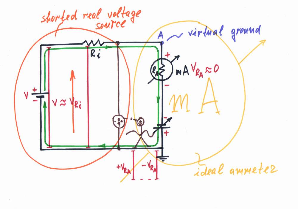
Actually, the additional source helps the input source injecting exactly as much voltage as it drops across the ammeter.
Note that the two voltage sources are connected in series, in one and the same direction (+ -, + -) so that their voltages are added.
< prev step - 0 - 1 - 2 - 3 - 4 - 5 - 6 - next step >
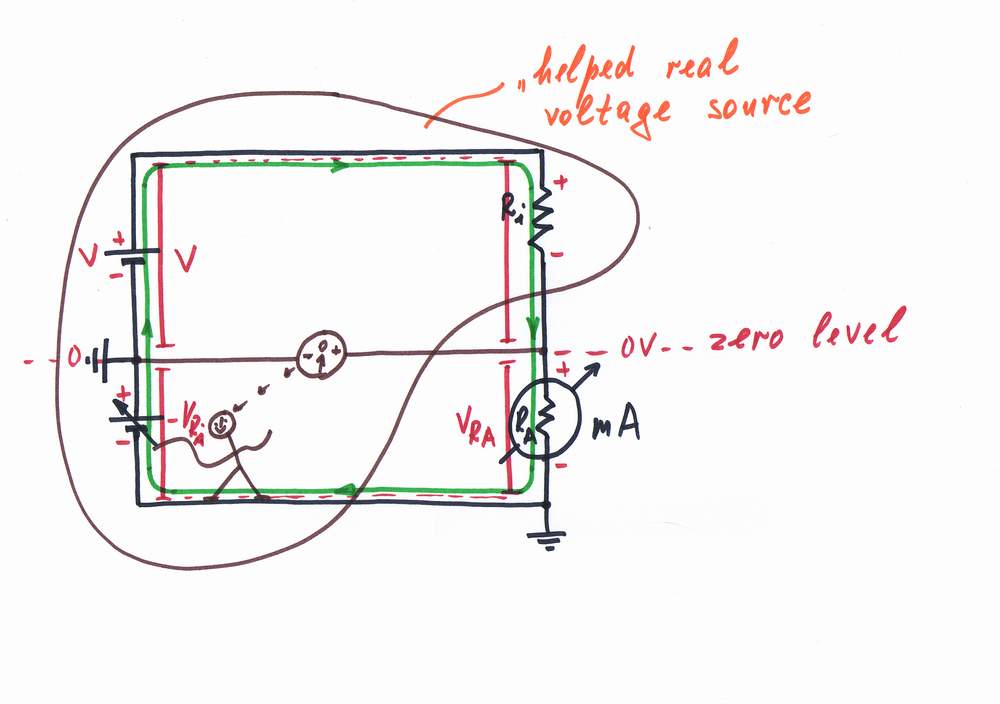
Now, we have only to replace the "op-amp man" with a real op-amp. It doses the voltage of the power supply thus producing a compensating voltage -VRA. Thus, the combination of an op-amp and a steady battery acts as a regulated supplementary battery.
The op-amp "observes" the potential of the point A (the difference between the two voltages) and changes instantly its output voltage so that the point A stays always at zero volts (it acts as a virtual ground). Doing that, the op-amp compensates the "harmful" voltage drop across the ammeter by copying and adding it to the voltage of the input source (in other words, it "helps" the input source).
< prev step - 0 - 1 - 2 - 3 - 4 - 5 - 6 - next step >
"Cleaning" the circuit diagram (don't do it, if you are a real teacher!) Finally, we may remove all the "unnecessary" components of the picture (voltage bars, current loops, power supplies etc.) and thus we will get the classic circuit diagram of the op-amp ammeter:) It will be so simple, small, easy to memorize but yet... nonunderstandable! Even if we adorn this bare circuit diagram with all kinds of formulas, it will remain still nonunderstandable!
But this humble circuit diagram is extremely convinient for writing; so, we may put it into the latest recipe book on electronics and serve it to the poor students :).
Here, the basic idea is hidden...
Related internal links:
What does the op-amp do in the circuit of op-amp ammeter?
Analog electronics 2004 - Class 9
How I revealed the secret of parallel negative feedback circuits
Related external links:
circuit-fantasia > circuit stories > building circuits > op-amp ammeter short