circuit-fantasia > circuit stories > building circuits > Op-amp RC integrator (short)
Building Circuits on the Whiteboard
Op-amp RC Integrator (short version)
< prev step - 0 - 1 - 2 - 3 - 4 - 5 - next step >
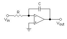
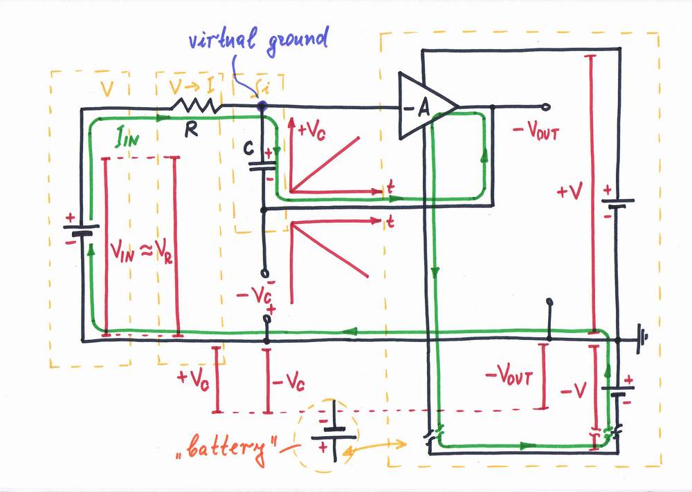
As the inverting input of the op-amp is at virtual ground (0 V) the input current is constant and determined only by the input voltage VIN and the resistor R. The output voltage Vout is a copy of the voltage across the capacitor C.
< prev step - 1 - 2 - 3 - 4 - next step >
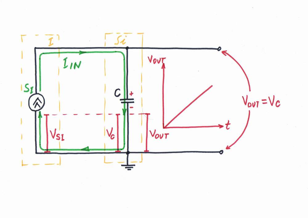
If you drive a capacitor by a constant current source, it functions as an ideal current-to-voltage integrator.
< prev step - 1 - 2 - 3 - 4 - next step >
In order to build an integrator with voltage input, connect a voltage-to-current converter before the circuit.
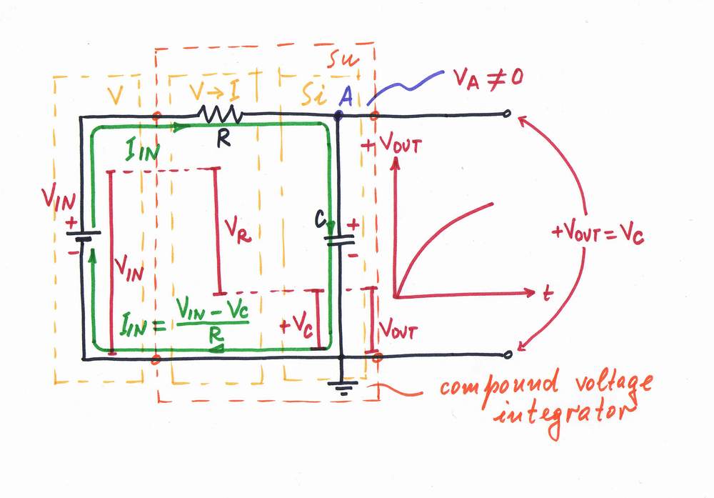
Only, the voltage drop VC across the capacitor C affects the input current and the output voltage changes exponentially trough the time.
< prev step - 1 - 2 - 3 - 4 - next step >
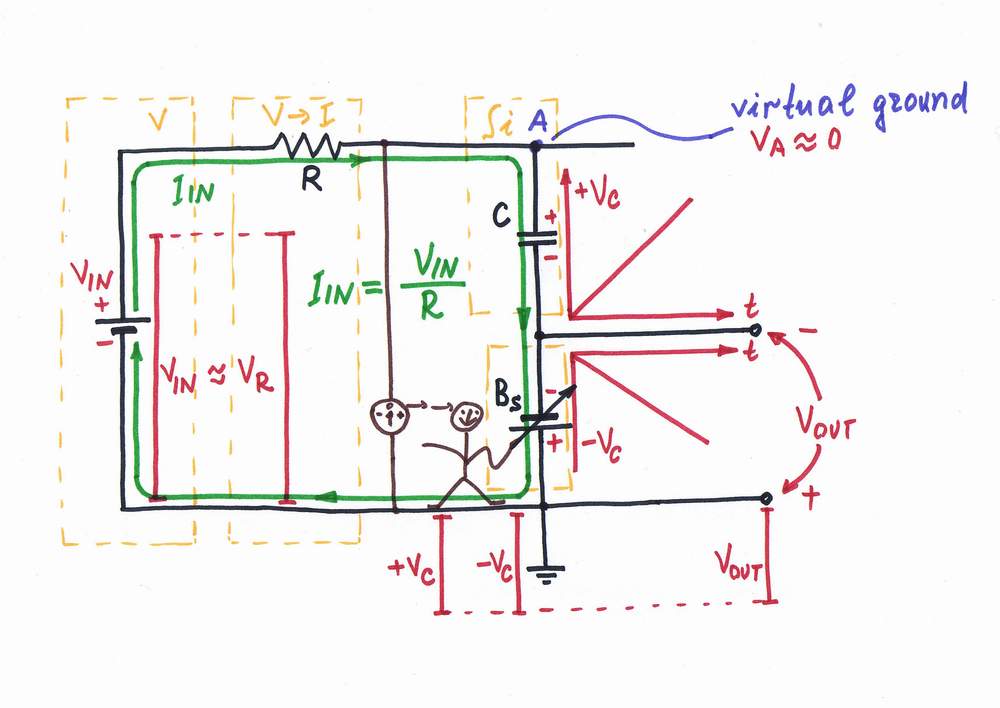
In order to help the input voltage source, connect an additional supplementary battery BS and adjust its voltage so that VS = -VC.
< prev step - 1 - 2 - 3 - 4 - next step >
Finally, replace the "manual" op-amp with a real one; then use its compensating voltage as an output of the integrator.
Finally, remove all the "unnecessary" components of the picture to get the classic circuit diagram of the op-amp integrator:).
Now, you may place this simple but nonunderstandable diagram at any recipe book on electronics:).
circuit-fantasia > circuit stories > building circuits > Op-amp RC integrator (short)