home - list of papers - conflict principle (the first story)
![]() The 2nd Int. Conference COMPUTER SCIENCE' 2005, Chalkidiki, Greece , September 30, 2005
The 2nd Int. Conference COMPUTER SCIENCE' 2005, Chalkidiki, Greece , September 30, 2005
Cyril Svetoslavov Mechkov
Department of Computer Systems, Technical University of Sofia,
e-mail: cyril@circuit-fantasia.com, site: http://www.circuit-fantasia.com
Abstract : In [1], a universal heuristic principle conflict causes amplification lying in the root of circuits with dynamic load was established. In this work, the conflict principle is improved in order to cover the more sophisticated circuits with controlled dynamic load. First, a general heuristic principle dramatic conflict causes high amplification is revealed. For this purpose, a few analogies of the phenomenon are generalized into a block scheme of two identical negative feedback followers interacting each other. Then the dramatic conflict principle is used as a tool for analysing various electronic circuits with controlled dynamic load (CMOS, transistor stages with current mirror collector dynamic load, op-amp internal structures etc.) Finally, a universal procedure for building all kinds of electronic circuits with controlled dynamic load is established.
Keywords: dynamic load, negative feedback circuits, differential amplifier, CMOS circuits, current mirror.
1. INTRODUCTION. Extracting the universal conflict principle from our routine [1], we have managed to reveal the secret of a large class of electronic circuits with dynamic load - common-base stage, emitter-coupled circuits, transistor stages with collector dynamic load, op-amp internal structures etc. In all these circuits we have gained amplification by causing a conflict between two electrical sources (voltage or current ones). In this paper, we have to find a way to strengthen the conflict between the sources, in order to gain more amplification in circuits with dynamic load.
 |
 |
 |
Fig. 1 |
||
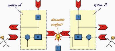
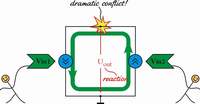
2. IMPROVING THE CONFLICT PRINCIPLE. In order to change the output quantity of a negative feedback system (a follower or an amplifier), we admittedly apply the input quantity at the input of the system. But there is another possibility to control the output quantity to apply the input quantity directly to the output of a negative feedback system (stabilizer). As a result, a conflict arises; the follower reacts to our intervention striving to keep steady its output value. In this way, the follower transmutes itself into an amplifier [1].
Then we have evolved this powerful idea by connecting together the outputs of two identical negative feedback systems. Thus we have obtained a symmetrical structure where the two systems have already worked at equal conditions fig. 1. If we change the input quantity X1 and X2 differentially in opposite directions, the conflict between the two systems becomes dramatic. The popular games of arm wrestling and tug of war are good examples of this phenomenon.
3. INVESTIGATING DRAMATIC CONFLICTS IN ELECTRONIC CIRCUITS. Again, we may apply the principle derived in order to understand the more complicated electronic circuits with controlled dynamic load. As before, we may encounter two kinds of conflicts - between voltage sources ( in stages with voltage dynamic load) and between current sources (in stages with current dynamic load). In the first case, the reaction of the disturbed system is a current one; in the second case, the reaction is a voltage one.
Fig. 2 |
3.1. Circuits with voltage dynamic load. By perceiving dramatic conflicts between two voltage sources we may realize profoundly a set of new classic electronic circuits differential amplifier, CMOS circuits, op-amp instrumentation amplifier, some op-amp internal structures of the input stages etc.
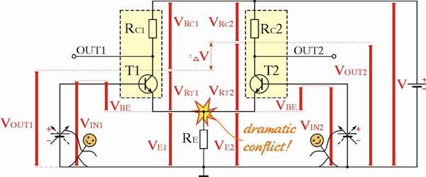
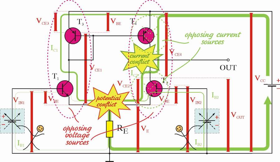
3.1.1. Differentional amplifier. Following the improved conflict idea we may present the classic circuit of a differential amplifier as a double system consisting of two emitter followers [2] - transistors T1 and T2, which emitters are connected to the common resistor RE - fig. 2. If we change differentially the input voltage V1 and V2 (i.e. simultaneously and in opposite directions), a dramatic conflict between the two transistors appears. They fight each other - T1 strives to increase the voltage drop across the emitter resistor while T2 strives to decrease it and v.v. The two transistors act with equal force on the conflict point (upper part of the resistor Re), whose voltage remains steady. The reaction of both the followers the voltage drops VRC1, VRC2 across the collector resistors and their complements VOUT1, VOUT2 are symmetric and proportional to the degree of the conflict; they play the role of the output voltages of the circuit.
Fig. 3 |
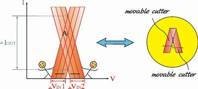
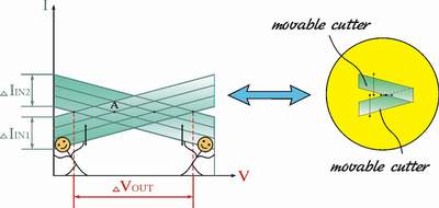
A geometrical interpretation of the phenomenon is showed on fig. 3. When we change the input voltages VIN1 and VIN2 their IV-characteristics move horizontally in opposite directions remaining parallel to themselves. The working point A slides vertically over both the dynamic IV-characteristics. As the two characteristics are almost in parallel, small variations of the input voltage cause very significant variations of the output current. We may think again of this interpretation as a geometrical amplifier (we might see also a similar geometrical phenomenon in a two-sided guillotine).
Fig. 4 |
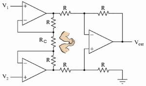
3.1.2. Op-amp instrumentation amplifier. Similarly, we may present the classic circuit of an op-amp instrumentation amplifier as a double system consisting of two op-amp followers, which outputs are interconnected with a common resistor RC. If we change differentially the input voltage V1 and V2 (i.e. simultaneously and in opposite directions), a dramatic conflict between the two op-amps appears. They fight each other - the upper op-amp strives to increase/decrease the voltage of the middle point inside the common resistor RC while the lower op-amp strives to decrease/increase it.
The two op-amps act with equal force on the conflict middle point, whose voltage remains steady. The reaction of both the op-amps their output voltages in point 3 and 4, are symmetric and proportional to the degree of the conflict. The second op-amp stage just converts the differential signal into a single ended one.
3.2. Circuits with current controlled dynamic load.
Fig. 5 |
3.2.1. Differential amplifier with current mirror loads. By using the dramatic conflict principle we may reveal the secret of another popular circuit - differential amplifier with current mirror acting as collector load [3] fig. 6. In this circuit, the transistors T2 and T4 function as voltage controlled current sources fighting each other - fig. 5. The input voltage V1 drives the current source T4 (through the transistors T1 and T3); the input voltage V2 drives directly the current source T2.
Let's now change differentially the input voltage V1 and V2 - for concreteness, let's V1 increases and V2 decreases. As a result, T4 strives to increase the common current while the transistor T2 strives to decrease the common current . This conflict causes a significant change of the voltage of the common point between the collectors. This voltage acts as an output voltage VOUT determining the high amplification of the circuit [3].
Fig. 6 |
Fig. 7 |
In the geometrical interpretation - fig . 7, when we change the input voltages VIN1 and VIN2, the two IV-characteristics move vertically in opposite directions remaining parallel to themselves. The working point A slides horizontally over both the dynamic IV-characteristics. As the two characteristics are almost in parallel, small variations of the input voltage cause very significant variations of the output voltage. We may think again of this interpretation as a geometrical amplifier (we might see also a similar geometrical phenomenon in a two-sided guillotine).
4. BUILDING ELECTRONIC CIRCUITS BY USING THE DRAMATIC CONFLICT PRINCIPLE. Once we have revealed the basic idea behind electronic circuits with controlled dynamic load, we may build them in the process of teaching. Then, we may build any even completely new circuits of this class applying the building procedure below:
BUILDING PROCEDURE 1. Get two negative feedback systems (usually voltage followers). 2. Connect together the outputs of the systems. 3. Vary differentially the input quantities. 4. Get the circuit reactions (usually voltages) as an output quantity. |
5. CONCLUSIONS. In this paper, we have managed to improve the powerful conflict principle [1], in order to get more amplification. By using the dramatic conflict idea we have processed a large class of electronic circuits with controlled dynamic load.
We may use the results obtained for the purposes of teaching and circuit design.
6. REFERENCES.
6.1. Papers.
[1] Mechkov, C. (2005) "Investigating, presenting and building electronic circuits with dynamic load by using the heuristic conflict principle". Computer Science'2005, Chalkidiki, Greece.
[2] Mechkov, C. (1999) Looking for an idea The differential amplifier: a dramatic fight between voltage sources . Engineering Review (1311-0470) 3, p. 22 .
[3] Mechkov, C. (1999) Looking for an idea Dramatic current conflicts in amplifiers with controlled dynamic load. Engineering Review (1311-0470) 3, p. 18.
6.2. Links. Here are additional internal links related to the conflict principle:
My great circuit penetrations is a collection of circuit concepts I have realized.
Opposing systems with negative feedback shows that like people in society negative feedback systems may interact i.e. opposing each other.
List of circuit conflicts is a weekly updated column about conflict circuit phenomenon.
Transistor Circuits with Negative Feedback shows the content of Class 7 from the course on Analog electronics.
How to invent electronic circuits is a series of 17 papers that I prepared for Popular Electronics magazine in 1999 (3 MB pdf, BG version only). Two of them are dedicated to the dramatic conflict principle:
Paper 11. Dramatic conflict between voltage sources,
Paper 12. Conflicts between current sources.
Differential amplifiers is a scanned draft of my Lecture 6 (BG version only).
home - list of papers - conflict principle (another story)
Last updated, August 22, 2005