<< prev story circuit-fantasia > circuit stories > understanding circuits > diode shifted current source next story >>
What is the idea behind this circuit?
Transistor Current Source with Shifting Diode
(Transistor Bootstrapped RC Integrator)
Idea: Keeping a constant current by following voltage (bootstrapping) .
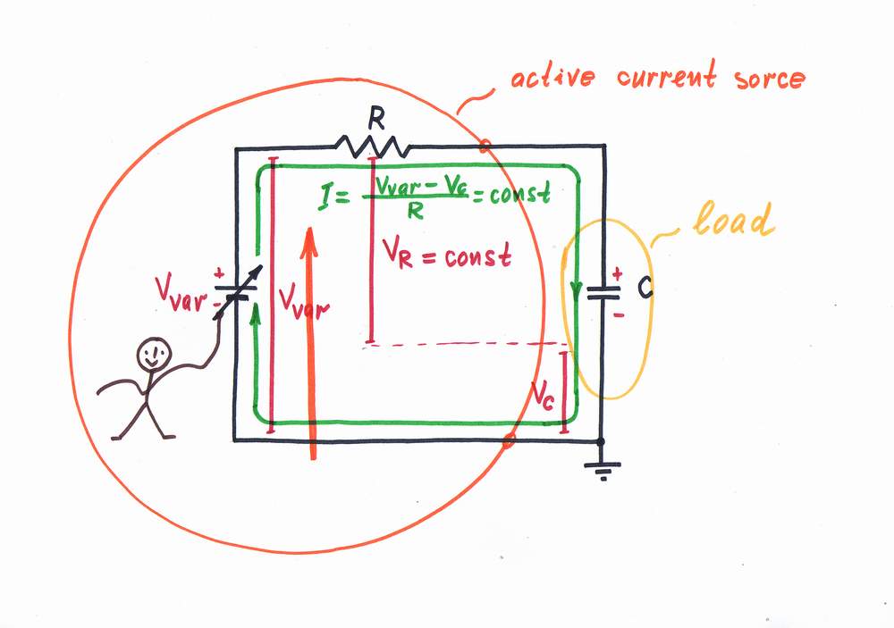
The simple current source is imperfect as the load affects the current (let's now suppose that the load is a capacitor C i.e. we consider an RC integrator). The voltage drop VC across the capacitor is harmful as it enervates the excitation voltage V thus decreasing the input current.
According to the basic idea above, we increase continuously the voltage Vvar with Vc, in order to compensate the voltage drop VC across the load. In this way, Vvar acts as a following voltage source keeping constant voltage difference Vvar - VC = const, which produces a constant current.
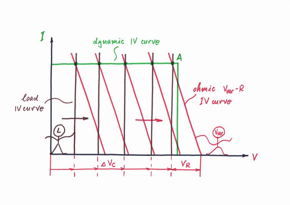
Graphically presented, when the capacitor charges its IV curve moves horizontally to the right remaining parallel to it. As the voltage source Vvar reacts to this intervention by increasing the voltage, its IV-characteristic moves also horizontally to the right remaining parallel to it. As a result, the working point A slides horizontally over the dynamic IV-characteristic of the constant current source obtained.
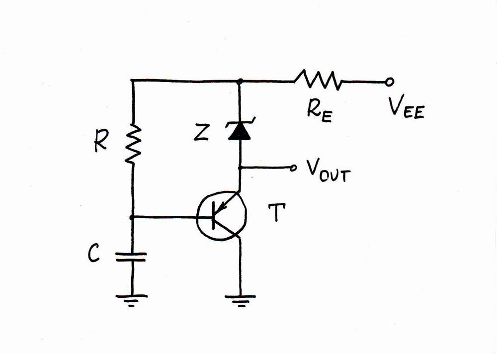
Implementation: Using an emitter follower as a following voltage source.
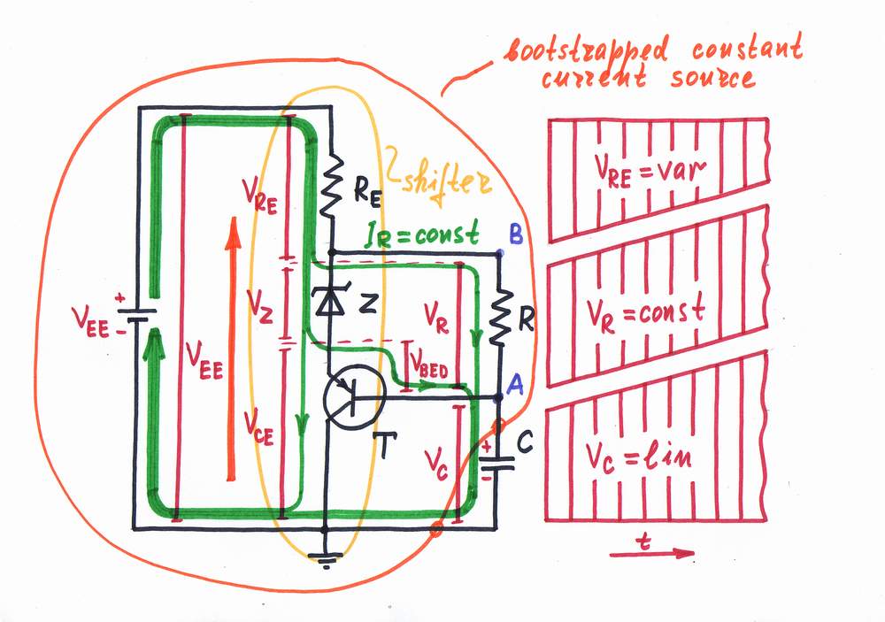
We may recognize this idea in the circuit of the BJT constant current source using following voltage compensation (i.e. the so called bootstrapping). First, the emitter follower implemented by the transistor T tracks the load voltage Vc (the potential of point A). Then, the zener diode Z lifts additionally the potential and applies it to the point B.
As a result, the potential of the point B follows the potential of the point A. The voltage difference VR = VA - VB across the resistor R stays steady and a constant current passes through the resistor R and the load C.
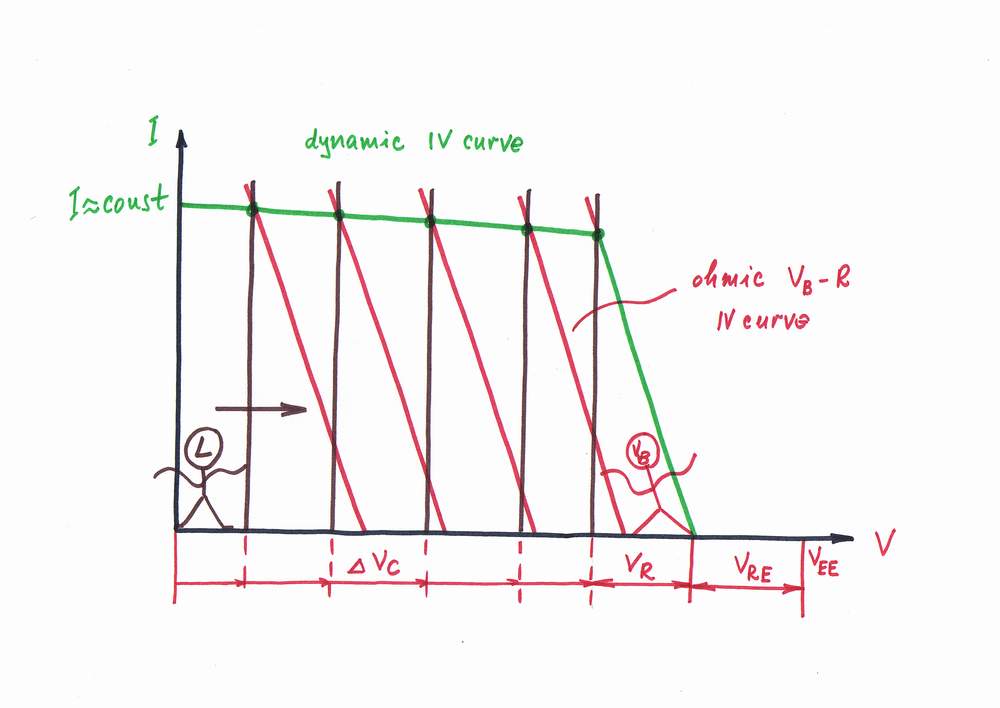
As the general graphical presentation, when the capacitor charges its IV curve moves horizontally to the right remaining parallel to it. The IV-characteristic of the shifted by the zener diode emitter follower moves also horizontally to the right remaining parallel to it. As a result, the working point A slides almost horizontally over the dynamic IV-characteristic of the constant current source obtained.
<< prev story circuit-fantasia > circuit stories > understanding circuits > diode shifted current source next story >>