Inventing Circuits on the Whiteboard...
Negative Impedance Converter with Voltage Inversion (VNIC)
Basic electrical circuit
Graphical representation
top < prev step - 1 - 2 - 3 - next step > end
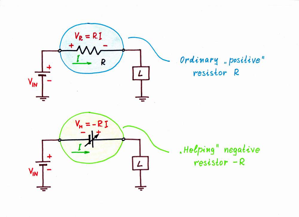
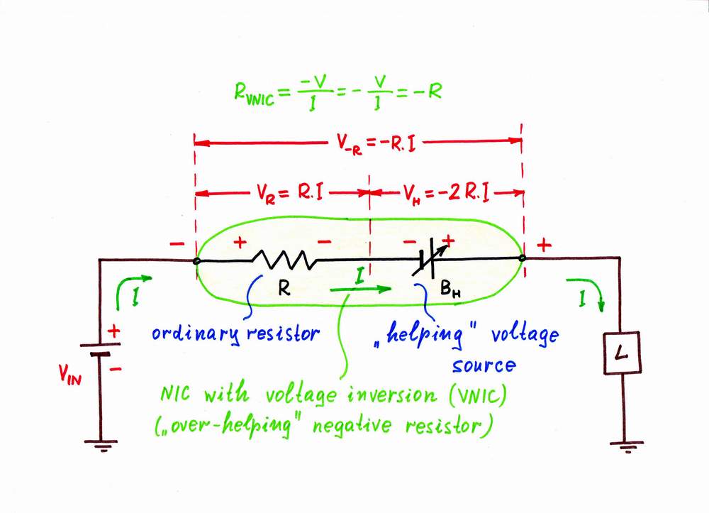
"Ordinary" versus "over-helping" negative resistance
top < prev step - 1 - 2 - 3 - next step > end
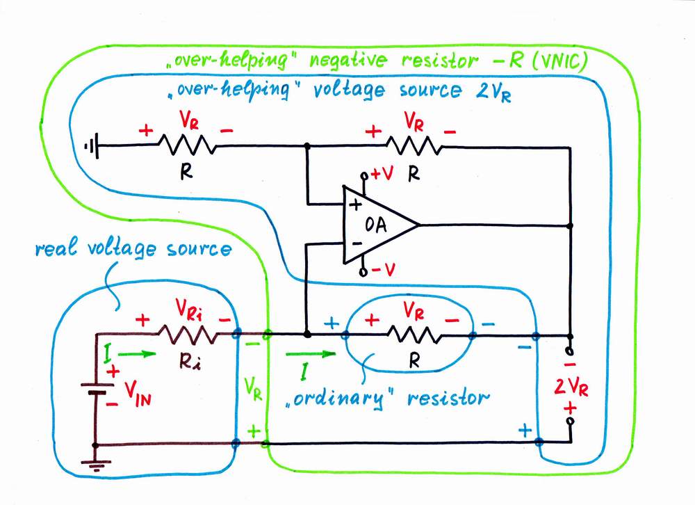
How to make a negative impedance converter (VNIC)
top < prev step - 1 - 2 - 3 - next step > end
Op-amp NIC with voltage inversion (VNIC)
circuit-fantasia > circuit stories > inventing circuits > VNIC
Last updated July 8, 2006