 Understanding Circuits on the Whiteboard...
What is the Idea behind a Constant Current Source (philosophy)?
Circuit stories about current source:
1. Ideal current source at ideal load conditions
2. Passive compound current source at ideal load conditions
Passive current source (shorened)
3. Passive compound current source at real load conditions
Passive current source (real loaded)
4. Active current sources with varying the internal resistance
Bipolar transistor current source
Field-effect transistor current source
5. Active current sources with varying the voltage
Bootstrapped transistor current source with shifting diode
Bootstrapped transistor current source with shifting capacitor
6. Active current sources with adding a voltage
Op-amp inverting current source for floating load
7. Active current sources with adding a current
How to build Howlend op-amp current source (version 1)
How to build Howlend op-amp current source (version 2)
8. Active current sources with negative feedback
Negative feedback transistor current source
Op-amp non-inverting current source for floating load
Voltage regulator acting as a current source
Color key: links to this page, links to other stories about current sources from this web site, external links to other web resources
 Problem. Have you ever thought about the fact that almost all the natural electrical sources are constant voltage sources? Actually, there are not constant current sources in the nature (excepting inductor and Van der Graaf generator). So, if we need a current source, we have just to build it!
In this story on the whiteboard, we will reveal the current source philosophy. Here we will attempt to answer the questions: What is inside a constant current source? How is it built? How many basic ideas behind different current sources exist? What is the best of them?
In order to reveal the truth behind these famous circuits, we will discover all the possible ways of current source creating. If you want to know more about the concrete implementations, follow the links pointing to the according concrete pages.
top < prev step - 1 - 2 - 3 - 4 - 5 - 6 - 7 - next step > end
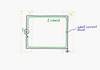
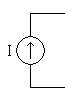
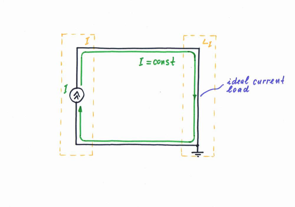
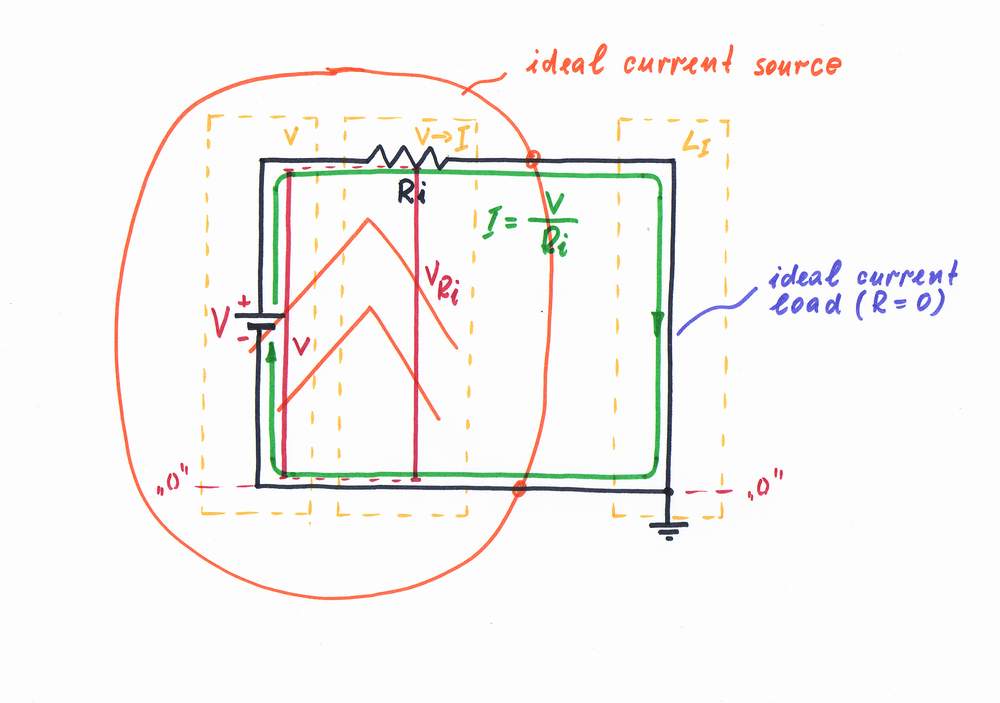
Ideal current source in ideal load conditions. Every, even the most elementary electrical circuit, consists at least of a source and a load. Let's now consider the most elementary current supply circuit containing an ideal current source and an ideal current load.
A current source likes a load with zero resistance and voltage (see below to know why). So, if the current source output is shorted (with a piece of wire), it will behave as an ideal current load LI with zero resistance.
top < prev step - 1 - 2 - 3 - 4 - 5 - 6 - 7 - next step > end
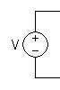
Passive compound current source in ideal load conditions. Now, let's see what a simple current source contains... Looking at the circuit, we may recognize two consecutively connected circuit building blocks: a constant voltage source V and a humble resistor Ri acting as a simple voltage-to-current converter.
Paradox. Note, that this is the simplest current source. Only, as it works at ideal load conditions (shorted output), it behaves as a perfect current source - I = V/Ri.. Do you agree?
If you want to know more about the simple current source, visit the page below:
What is the idea behind a shortened simple current source?
See also: Voltage causes current, Voltage-to-current converter,
top < prev step - 1 - 2 - 3 - 4 - 5 - 6 - 7 - next step > end
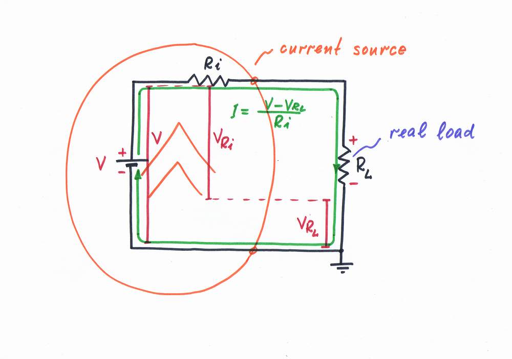
Passive compound current source at real load conditions. But this compound current source is created with a purpose to use its current. So, a real load is usually connected at the output of the circuit. For concreteness, let's consider the case when the load has an ohmic resistance RL (e.g. an imperfect ammeter with internal resistance).
Problem. Only, we see a problem here - the load resistance RL affects the current. Or, the voltage drop VRL across the load is harmful as it enervates the excitation voltage V. Now, the voltage difference V - VRL determines the current instead the voltage V. As a result, the current decreases. What do they do, in order to decrease the error?
Remedy 1: keeping a comparatively constant current by depreciating the load. We may see this well-known electrician's rule in any classic electricity book. See the page below to know more:
What is the idea behind a real loaded simple current source?
See also: Voltage causes current, Voltage-to-current converter,
top < prev step - 1 - 2 - 3 - 4 - 5 - 6 - 7 - next step > end
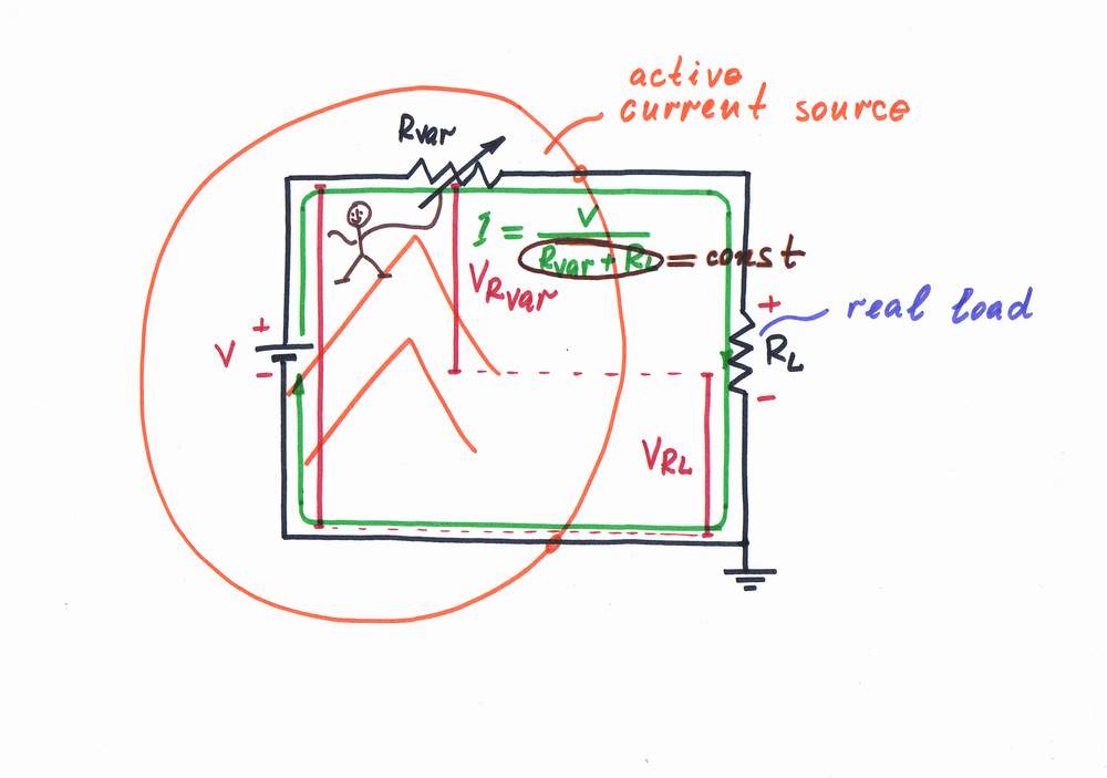
Remedy 2: keeping a constant current by varying the internal resistance. If we scrutinize a lot of current source circuits, we may find out a powerful basic idea about constant current keeping: change Rvar (Ri) to the opposite direction, in order to keep up a constant total circuit resistance (Rvar + RL = const). In this arrangement Rvar acts as a resistor with dynamic resistance, which complements RL to the full constant circuit resistance.
Experiment: We may implement this idea in the laboratory by connecting two rheostats acting as RL and Ri. Move randomly the RL slider; I will watch your actions and will move the RL slider to the same but opposite position. What about the current? Is it constant?
In the classic transistor current sources, a BJ or a FE transistor does this donkey work:). See the page below to know how.
What is the idea behind a simple bipolar transistor current source?
top < prev step - 1 - 2 - 3 - 4 - 5 - 6 - 7 - next step > end
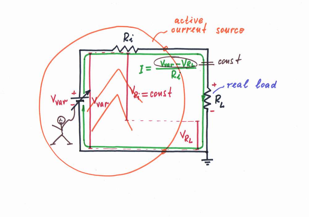
Remedy 3: keeping a constant current by varying the voltage. Browsing through the current source circuits, we may find out a similar basic idea: change the excitation voltage Vvar (V), in order to compensate the voltage drop VRL across the load. In all these circuits, Vvar acts as a following voltage source keeping constant voltage difference (Vvar-VRL=const), which produces a constant current.
Experiment: Now, move again the RL slider. I will replace the steady voltage source V with a varying (dynamic) source Vvar and will connect a voltmeter across the load. Then, looking at the voltmeter, I will move the Vvar knob to the appropriate direction and position. What about the current? Is it constant?
In this class of current source circuits, a transistor or an op-amp does this boring work. See the pages below to know how:
A bootstrapped transistor current source with shifting diode,
A bootstrapped transistor current source with shifting capacitor,
top < prev step - 1 - 2 - 3 - 4 - 5 - 6 - 7 - next step > end
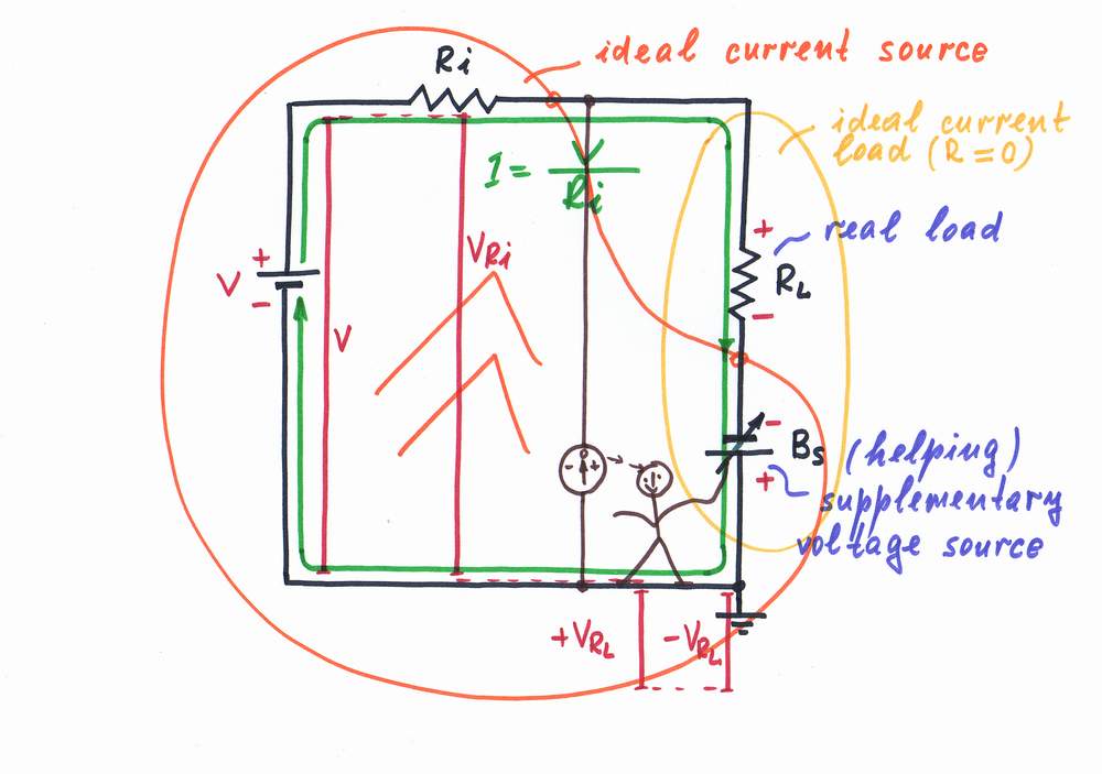
Remedy 4: keeping a constant current by adding a voltage. The two ideas above are good enough but in many cases we can change neither resistance nor voltage (e.g. imagine that V and Ri are located at long distance). Then, the next genius idea - removing voltage by an "antivoltage" - will help us.
In this class of circuits, the harmful voltage VRL is compensated with an equivalent "antivoltage" -VRL. In other words, an additional voltage VRL is added to the excitation voltage source V. As a result, a constant current I = V/Ri passes through the real load.
Experiment: Move, as usual, the RL slider. I will add an additional supplementary voltage source Bs and will adjust its voltage VBs = -VRL by looking at a zero indictor. What about the current?
Again, an inverting op-amp can accurately do this routine work:
top < prev step - 1 - 2 - 3 - 4 - 5 - 6 - 7 - next step > end
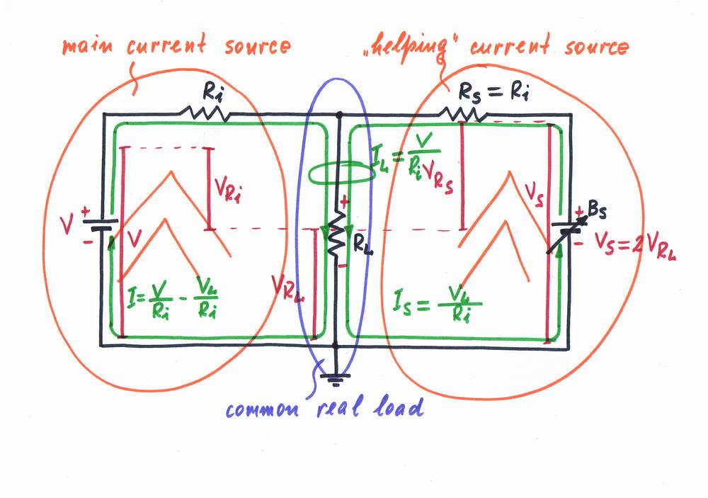
Remedy 5: keeping a constant current by adding a current. As we can see, the current I decreases with VL/Ri because of the load voltage drop VL. In the circuits above, we aided the exciting voltage source by an additional supplementary voltage source. There are similar circuits, where the voltage source is aided by injecting an additional current Is = VL/Ri produced by another "helping" current source. It is implemented again by connecting a "helping" voltage source Bs through another resistor Ri to the load. This idea is proposed by Howland.
Experiment: Move again the RL slider. I will connect a voltmeter across the load and will move the Vs knob so that Vs = 2VRL. What about the current? Is it constant, as we have supposed?
In these circuits, a non-inverting op-amp accurately does this work:
top < prev step - 1 - 2 - 3 - 4 - 5 - 6 - 7 - 8 - next step > end
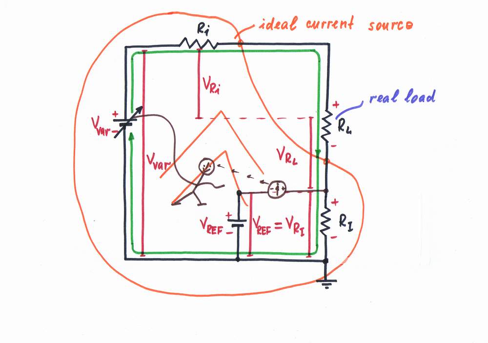
Remedy 6: keeping a constant current by negative feedback. So far, the constant current is kept without using negative feedback.
Of course, the best solution is to monitor the current I while changing the resistance Ri or voltage Vvar. In these circuits, a constant voltage VRI is kept across a constant resistor RI acting as a current-to-voltage converter. As a result, a stable current I = VREF/RI passes through the load.
Experiment: Let's connect a reference voltage VREF and a zero indicator in the circuit; then move the RL slider. I begin moving the Vvar (Ri) knob so that VRI = VREF. What about the current?
Of course, the favorite electronic elements (a transistor, an op-amp, voltage regulator etc.) do this work in the various circuits of the negative feedback current sources:
Negative feedback transistor current source,
Op-amp non-inverting current source,
Voltage regulator acting as a current source.
Internal links to html pages and flash movies:
Analog electronics 2004 - Class 1
Analog electronics 2004 - Class 9
How I revealed the secret of parallel negative feedback circuits
External links:
Wikipedia: Current source, Voltage source
Lessons in Electric Circuits: Basic concepts in electricity, Experiments
circuit-fantasia > circuit stories > understanding circuits > current source (philosophy)