 Inventing Circuits on the Whiteboard...
How do We Make Decreased, Zero and Negative Resistance?
From many years, I have been thinking about the phenomenon of negative resistance. Finally, I have managed to build my own philosophy about it; now, I would like to share my penetrations with you.
In this story, I actually show how we can create electronic circuits with negative resistance. Then, why have we to consider decreased and zeroed resistance before?
Trying to explain the unexplained things in electronics to my students, I have been noting that the large part of the truth about circuit phenomena is hidden in the movement from simple to complex circuits than in the final perfect circuit solutions. That is why, I ever show the evolution of electronic circuits to my students by reinventing them in consecutive logically connected steps revealing the basic ideas at every stage.
We are human beings needing something more than scientific facts, reports, formal explanations and definitions. In order to really comprehend the phenomenon of negative resistance (and of every new thing in this life), we need first to know what the general idea behind it is. Only, basic circuit ideas are in fact "non-electrical". They do not depend on the specific implementation (tube, transistor, op-amp etc.); they are eternal. So, we may find them in our routine.
Generally speaking, we may observe this phenomenon in situations where someone (something) interferes to some extent in our life. He/she/it may help or impede us in three degrees (under-, exactly- or over-). Negative resistance represents the last degree when someone "over-helps" or "over-impedes" us. Similarly, in electrical circuit, a current may flow through components having ohmic, decreased, zeroed or negative resistance.
So, the best way to reveal the negative resistance phenomenon is to show (reinventing step-by-step the circuits) the evolution of "ordinary" ohmic resistors into negative ones.
Internal links (from this page):
1. Starting point: An ordinary (ohmic) resistance
2. Investigating the ordinary resistance
3. Decreasing the resistance by varying the voltage slightly
4. Remedy: Removing voltage by an "antivoltage"
5. Obtaining a negative resistance by varying the voltage considerably
Other links from this site:
How do we create dynamic resistance?
What is the idea behind an op-amp inverting current source?
Reinventing transimpedance amplifier
How do We Build an Op-amp Ammeter?
How do We Build an Op-amp Integrator?
How I revealed the secret of parallel negative feedback circuits
External links:
Wikipedia: Ohmic device, Resistor,
Negative resistance, Negative impedance converter,
Another fresh viewpoint at negative resistance,
What is the basic idea behind negative impedance converter (NIC)?
Color key:
Links: this page, other my pages, external, multimedia, handmade.
Text: analogies, conclusions.
Basic electrical circuit
Graphical representation
top < prev step - 1 - 2 - 3 - 4 - 5 - next step > end
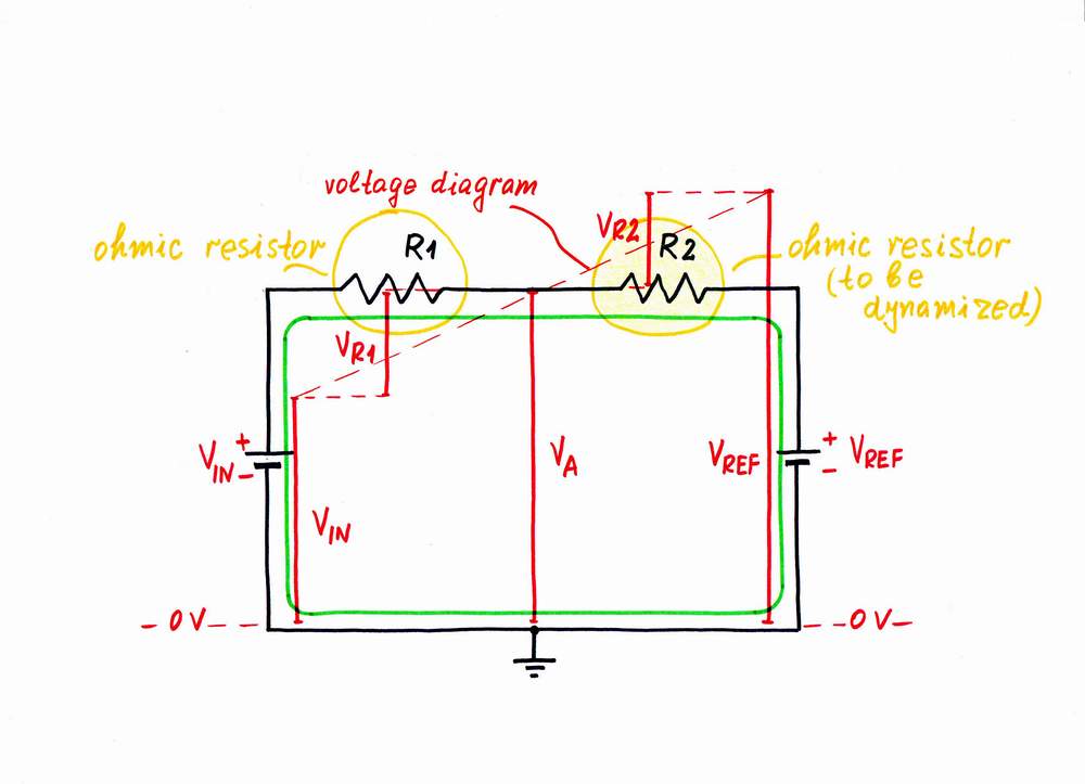
As we know from our routine, we usually experience a steady resistance when we implement our purposes. In electricity, we name these elements with steady resistance ohmic resistors. For example, let's consider again a simple circuit consisting now of four components: two voltage sources - VIN and VREF, and two ohmic resistors - R1 and R2. Again, you might think of this circuit as two resistors R1 and R2 connected in series to a compound voltage source with a voltage V = VIN + VREF. Or, you might discern here the famous circuit of a parallel resistive summer R1-R2, which sums the two voltages VIN and VREF. Finally, you might imagine that we have connected two real voltage sources to each other: the first - with voltage VIN and internal resistance R1, the second - with voltage VREF and internal resistance R2.
Starting point: An ordinary (ohmic) resistance
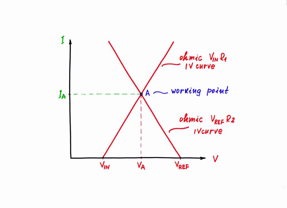
In order to present graphically the circuit operation, we have to superimpose the IV curves of the two real voltage sources - VINR1 and VREFR2, on the same coordinate system. In this arrangement, the intersection point A (the so called working or quiescent point here) represents the current (local) magnitudes of the voltage VA and the current IA.
The two resistors R1 and R2 represent ordinary ohmic resistors. We may define their resistances on the graphical representation:
R1 = (VA - VIN)/IA and R2 = (VREF - VA)/IA
top < prev step - 1 - 2 - 3 - 4 - 5 - next step > end
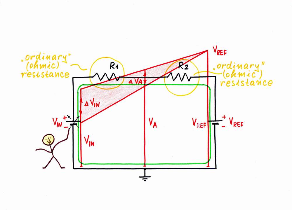
Let's now investigate the circuit. For this purpose, first connect a voltmeter between the middle point A and the ground; then, connect an ammeter in series with the resistors. By varying the voltage VIN as an input and observing the variations of the voltage VA as an output, we can "feel" the presence of both the ordinary ohmic resistances R1 and R2. Maybe, you have already noted that the circuit investigated acts as a voltage divider.
In order to see the invisible electrical attributes, we may superimpose voltage diagram and current loop onto the circuit diagram.
Investigating the ordinary resistance
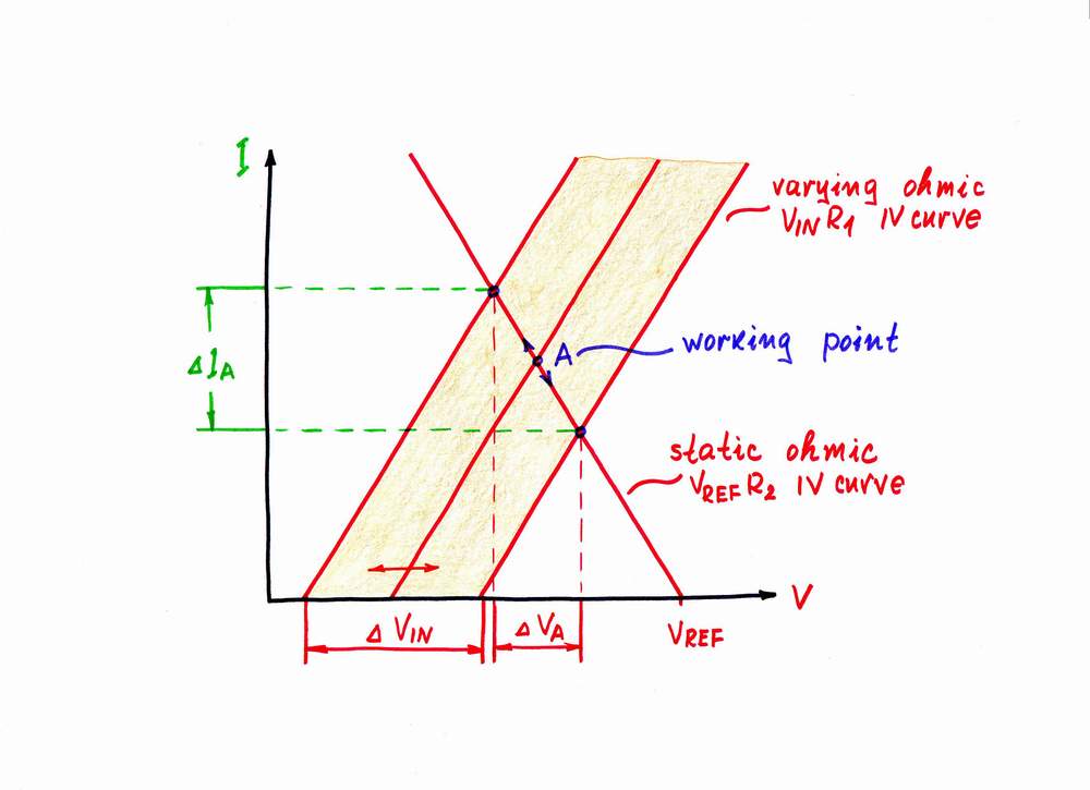
On the graphical representation, when you vary the voltage VIN of the input voltage source, its (your) IV curve moves horizontally. As a result, the working point A slides over the IV curve of the second real voltage source VREFR2.
Here, the slope of VREFR2 IV curve represents graphically the resistance R2. It is a "static" resistance as it does not depend on the location of the working point A. Note that it is equal to the so called differential resistance - R2 = (VREF-VA)/IA = Rd = dVA/dIA.
top < prev step - 1 - 2 - 3 - 4 - 5 - next step > end
As we know, there are also many situations in our life where someone helps us injecting (inconspicuously for us) an additional power. As a result, we experience a smaller resistance when we implement our purposes. Examples: parents help children, the husband refunds some part of the sum that his wife has spent, the pneumatic amplifier helps the driver when he presses the brake- or the clutch-pedal etc.
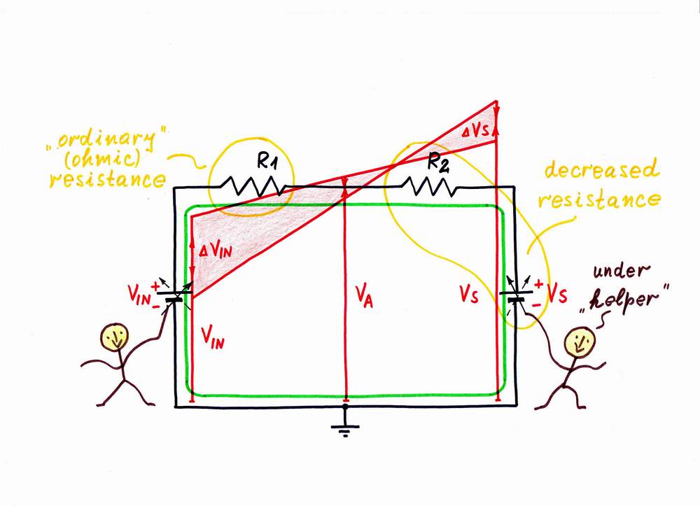
Let's apply this remedy to decrease the resistance of some resistor in the circuit above, e.g. R2. For this purpose, I will help the input voltage source VIN by a second supplementary voltage source Vs. In this way, I will dynamize its "static" resistance by using the well known powerful idea: I will change the helping voltage Vs while you vary VIN. Let's do it.
Well, when you increase the input voltage VIN, I decrease the voltage Vs and v.v. - when you decrease the input voltage VIN, I increase the voltage Vs. As a result, you have the illusion that the resistance R2 has decreased. You will "see" a new, decreased dynamic resistance Rd < R2. In electronics, the imperfect constant-voltage generating circuits act in this way.
Decreasing the resistance by varying the voltage slightly
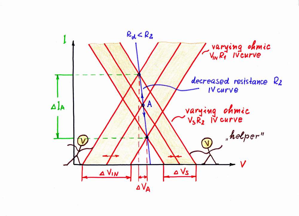
Let's now see again the graphical representation according to this idea. As above, when you increase the input voltage VIN, its IV curve moves horizontally from left to right. But now, as I decrease the voltage Vs at the same time, its IV curve moves from right to left. As a result, the working point A slides from left top to right bottom over a new more horizontal IV curve, which represents the new dynamic resistance Rd < R2.
And v.v., when you decrease the input voltage VIN, its (your) IV curve moves horizontally from right to left. In this case, I increase the voltage Vs at the same time; so, its (my) IV curve moves from left to right. The working point A slides now from right bottom to left top over the same IV curve.
Note again that you will see only the new IV curve of the dynamic resistor Rd; you will think that it is the IV curve of the previous resistor R2 but having already smaller resistance. It's a nice illusion, isn't it?
top < prev step - 1 - 2 - 3 - 4 - 5 - next step > end
Now imagine that the "helping" idea above is improved so that someone helps us injecting (inconspicuously for us) so much additional power that we do not experience any resistance when we implement our purposes. Examples: parents help children to such extent that they needn't to do anything:), the good husband refunds the whole sum that his wife has spent, the pneumatic amplifier helps the driver so much that he doesn't feel anything when he presses the brake- or the clutch-pedal etc.
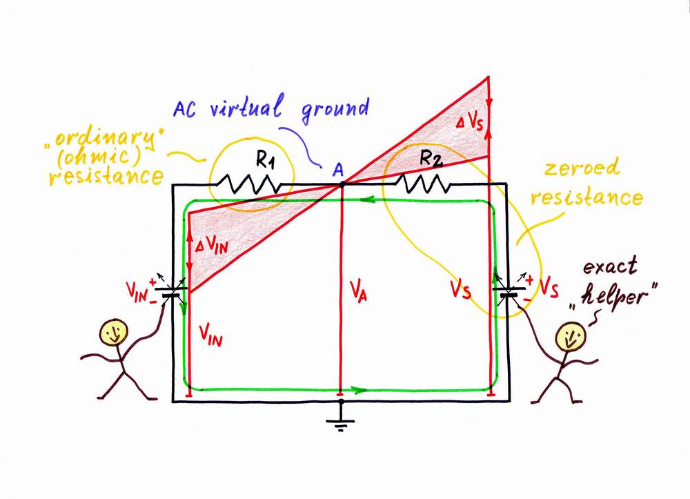
Let's apply this remedy, to zero the resistance R2. In order to help "exactly" the input voltage source VIN by the second supplementary voltage source Vs, I connect a zero indicator in point A and then change the voltage Vs so that VA = 0. In this way, I will keep a virtual ground in point A.
Well, when you increase the input voltage VIN, I decrease "exactly" the voltage Vs and v.v. As a result, you have the illusion that the resistance R2 has disappeared. You will "see" a new, zeroed dynamic resistance Rd = 0. All the op-amp inverting circuits with negative feedback act in this way.
How I revealed the secret of parallel negative feedback circuits
Analog electronics 2004: Class 9
Reinventing op-amp inverting summer, Op-amp circuit builder
Transimpedance amplifier, My viewpoint at transimpedance amplifier
Zeroing the resistance by varying the voltage exactly
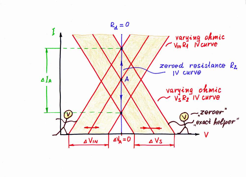
Let's now see again the graphical presentation according to this idea. As usual, when you increase the input voltage VIN, its IV curve moves horizontally from left to right. But now, as I decrease enough the voltage Vs at the same time, its IV curve moves "sufficiently" from right to left. As a result, the working point A slides from top to bottom over a new vertical IV curve, which represents the new zero dynamic resistance Rd = 0.
And v.v., when you decrease the input voltage VIN, its IV curve moves horizontally from right to left. In this case, I increase enough the voltage Vs at the same time; so, its (my) IV curve moves "sufficiently" from left to right. The working point A slides now from bottom to top over the same vertical IV curve representing the same zero dynamic resistance Rd = 0.
Note again that you will see only the new IV curve of the dynamic resistor Rd; you will think that it is the IV curve of the previous resistor R2 but having already zero resistance. It's a nice illusion, isn't it?
How do we create dynamic resistance - step 3?
What is the idea behind an op-amp inverting current source?
How do We Build an Op-amp Ammeter?
top < prev step - 1 - 2 - 3 - 4 - 5 - next step > end
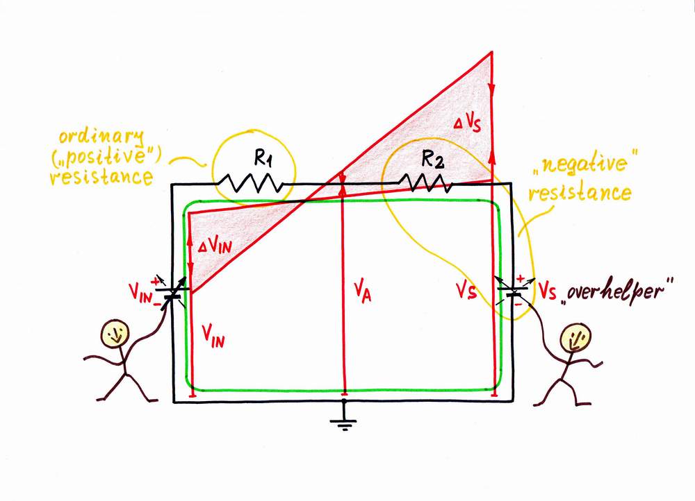
Finally, imagine that the "helping" idea is enormously improved so that our helper goes too far injecting many times more additional power that we actually need. Examples: parents over-help children doing their work as with a magic wand:), the excellent husband refunds the whole sum that his wife has spent and even adds additional money:), the pneumatic amplifier over-helps the driver so much that he has only to try pressing the pedal and it moves itself etc.
If I put this idea in practice, I will convert the ordinary "positive" resistance R2 into a negative one. Then let's do it helping "considerably" the input voltage source VIN by the second supplementary voltage source Vs.
When you increase the input voltage VIN, I decrease "considerably" the voltage Vs and v.v. As a result, the resistor R2 adds (instead to subtract) a voltage V = I x R2. You will "see" a new, negative dynamic resistance Rd = -R. Negative impedance converters (NIC) act in this way.
Obtaining a negative resistance by varying the voltage considerably
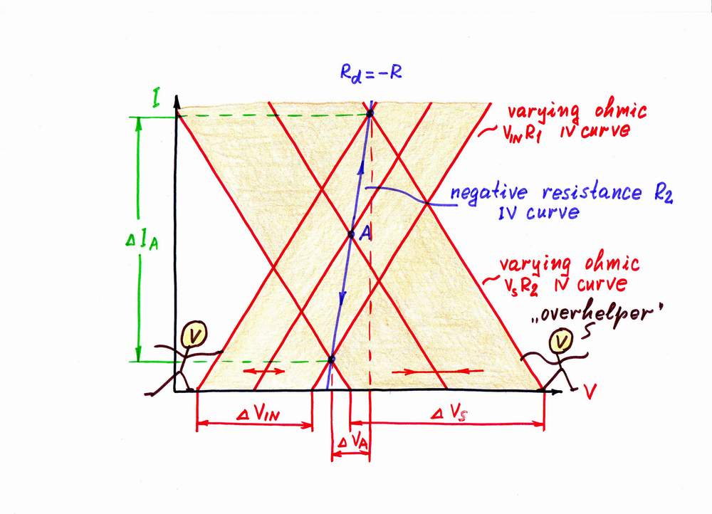
Let's finally see the graphical presentation according to this great idea. Again, when you increase the input voltage VIN, its IV curve moves horizontally from left to right. But now, as I decrease considerably the voltage Vs at the same time, its IV curve moves very fast from right to left. As a result, the working point A slides very fast from right top to left bottom over a new vertical IV curve, which represents the new negative resistance.
And v.v., when you decrease the input voltage VIN, its (your) IV curve moves horizontally from right to left. In this case, I increase considerably the voltage Vs at the same time; so, its (my) IV curve moves very quickly from left to right. The working point A slides now very quickly from left bottom to right top over the same IV curve.
Wikipedia: Negative resistance, Negative impedance converter,
Another fresh viewpoint at negative resistance,
What is the basic idea behind negative impedance converter (NIC)?
circuit-fantasia > circuit stories > inventing circuits > decreased resistance
Last updated April 7, 2007