home - bg - intro - contents - library - resources - feedback - digital
1 2 3 4 5 6 7 8 9 10 11
ANALOG ELECTRONICS - 2004
What we do at Class Exercise 3 (March 15-20, 2004)
Compound Passive Converters with Voltage Output
At Class 3 we will derive a further 8 elementary building blocks which we will put in the library; thus it will contain a total of 28 basic circuits so far:
| single-input devices (converters) |
voltage-to-voltage |
displacement-to-voltage |
| resistance-to-voltage (direct) |
resistance-to-voltage (reversed) |
| multi-input devices (various) |
ratio-by-voltage multiplier |
parallel voltage summer |
| parallel voltage subtractor (comparator) |
bridged circuit |
HISTORY. Almost two centuries ago, Ohm implemented his famous experiment. As they say, he stretched a piece of copper wire with length L and resistance R; then, he applied a voltage difference across the wire. Only, a problem appeared - this was the little wire resistance which loaded the source. That is why the ordinary battery did not work properly. Thus, Ohm decided to make a good voltage source using thermoelectric effect just invented by Seebek. Ohm dipped the one end of the thermocouple into boiling water and the other one - into a melting ice. Then, using an electroscope (?), a magnet needle (?) and maybe a lot of imagination, Ohm began studying the voltage distribution along the "resistor". If we reproduce now his famous experiment, using present-day measuring devices and no less imagination, we will "invent" more valuable passive circuits with which we will enrich our library of basic circuit building blocks.
EXPERIMENT. Instead a copper wire we will be smart enough to use some high resistive element (an open potentiometer, a conductive foam etc.). Thus we will not need a big power supply; so, we will make do with lower power supply. If we have not any supply, we might use a personal computer for this purpose. Furthermore, adding an analog-to-digital converter, we may use the same computer as a voltmeter. We may carry out this experiment virtually (in a hydraulic or electric version) or really.
VARYING. Now we will apply the well known technique for inventing new building devices varying some electrical attributes as an input and measuring other as an output.
|
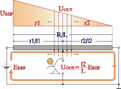
Walking along the resistive film and feeling the local potentials we get actually a potential diagram (we may assign drawing to the computer). In this way, we naturally "invent" a useful displacement-to-voltage converter (a sensor). Cool! This is how to push a mechanical attribute into a computer system.
|
|
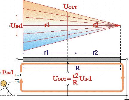
Then we fix the slider and begin changing the voltage from the left hand side. Thus we "invent" the legendary voltage divider acting here as a voltage-to-voltage converter.
See also another viewpoint at voltage divider.
|
|
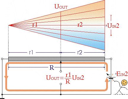
Similarly, if we change the voltage but now from the right hand side, we "invent" another voltage divider (controlled from the right hand side).
|
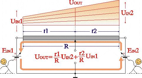 |
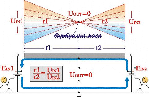
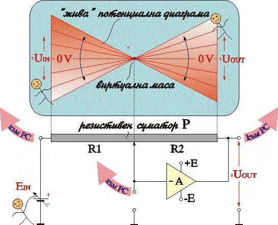
What happens if we vary both the voltages? Thus we "invent" the so valuable parallel voltage summer.
|
|
When the two voltages have a different polarity a wonderful virtual ground appears on the resistive film.
|
|
|
COMBINING. We may get the same devices as usual by building them from more elementary building blocks located in the library. Thus, if we connect in series a voltage-to-current converter and a current-to-voltage converter we get a compound voltage-to-voltage converter. Also, if we connect in series a resistance-to-current converter and a current-to-voltage converter (or a voltage-to-current converter and a resistance-to-voltage converter; and why not a resistance-to-current converter and resistance-to-voltage converter, i.e. a potentiometer?) we get a compound resistance-to-voltage converter. Finally, we assemble a bridge circuit building block using two voltage dividers. Here are building "formulas" for these compound building blocks:
voltage-to-voltage converter = voltage-to-current converter + current-to-voltage converter,
resistance-to-voltage converter (R1var) = resistance-to-current converter + current-to-voltage converter,
resistance-to-voltage converter (R2var) = voltage-to-current converter + resistance-to-voltage converter,
resistance-to-voltage converter (R1var, R2var) = resistance-to-current converter + resistance-to-current converter,
parallel voltage converter = voltage-to-current converters + current summer + current-to-voltage converter,
bridge circuit = voltage divider (left) + voltage divider (right) etc. Give more examples ...
A small project 1: DC VOLTAGE SHIFTING (LIFTING): Making input/output unipolar. Imagine you have a bipolar analog device (e.g. e.g. a split supplied op-amp amplifier) working with input voltages from -10V to +10V. Can you transform it to a unipolar device with input voltage range of 0V...+10V? Do the same with the bipolar circuit output.
A small project 2: DC VOLTAGE SHIFTING (DROPPING): Making input/output bipolar. Imagine you have a unipolar analog device (e.g. a single supplied op-amp amplifier, an analog-to-digital converter etc.) working with input voltages from 0V to +5V. Can you transform it to a bipolar device with input voltage range of -5V...+5V? Do the same with a device with a unipolar output (e.g. a digital-to-analog converter).
Related web sites
Let's now see what Gert has said about voltage dividers in his profoundly written electronics course.
2.3 Creating a voltage divider using resistors
Take a look at the picture on the right. We see three series connected resistors. We've already learned that the total resistance is 3k. So the current I will be 9V / 3k = 3mA. The voltage at point B, V B , equals 1k·3mA = 3V. (Do you still remember what is meant by 'voltage at point B'? It means: connect the red wire of the volt meter to point B and the black wire to ground.)
The general way of calculating the voltage across a resistor in a series connection is:
I = V source / R total , and V res = I·R. So:
There are three ways to calculate the voltage at point A:

- The total resistance of R2 and R3 is 2k, so
V A = 2k·3mA = 6V.
- The voltage across each resistor is 3V, so V A = 6V.
- Using the equation above: V A = 9V·(2k/3k) = 6V.
Does this mean that you can connect your 3V portable cassette player to point B? Well, of course you could, but don't expect it to work! The player acts like a resistor of, say, 50 ohms. That resistor is parallel connected with R3, resulting in a resistance of 47.6 ohms. So V B will drop to 9V·(47.6/2047.6) = 0.2V. And that will never be enough for your player.
Conclusion: If you design a voltage divider, don't forget to take the load into account! |
|
|
Send your questions, views and suggestions about this topic to cyril@circuit-fantasia.com
1 2 3 4 5 6 7 8 9 10 11
home - bg - intro - contents - library - resources - feedback - digital