Inventing Circuits on the Whiteboard...
 How to Compensate Resistive Losses by Parallel Connected Negative Resistor (Reinventing Negative Impedance Converter)
We have already known how to compensate resistive losses by series connected negative resistor (NIC). Maybe, it is possible to do the same by a parallel connected negative resistor? Yes, it is possible.
I have noted that, still from the Kirchoff's times, it is almost always possible to create two versions of circuits - a series and a parallel one. So, in this story, I will show to you another popular negative resistance application - compensating resistive losses by a parallel connected negative resistor. First, we will create an imperfect varying voltage source working at ideal load conditions. Then, we will load it, in order to see how it reacts to our intervention. Further, we will help the voltage source by canceling the load resistance by means of a negative resistance (NIC). Finally, we will compare this technique with the classical negative feedback compensation, in order to show what the advantages and disadvantages of the two approaches are.
As usual, in order to feel how a negative resistor does this magic, we will place ourselves in its place and begin performing its functions. Actually, this is another (third) story about reinventing negative impedance converter (NIC). I hope you have fun. Cyril
Internal links:
1. Starting point: Making a varying voltage source (unloaded)
2. Problem: Real voltage source loaded
3. Remedy: "Helping" the imperfect voltage source
5. Negative resistance implementation: NIC
Color key
Links: this page, other my pages, external, multimedia, handmade.
Text: analogies, conclusions.
top < prev step - 1 - 2 - 3 - 4 - 5 - 6 - 7 - next step > end
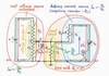
In nature, there aren't varying voltage sources; so, we have to build them. For this purpose, we just connect a varying voltage divider (a potentiometer P) after a steady voltage source V:
Steady voltage source + potentiometer = varying voltage source
In the beginning, imagine that there is no load connected (or, the load has an infinite resistance e.g. a digital VOM). Since there is no load current sucked from the circuit, the output voltage VOUT = r2/(r1 + r2). We may conclude that the simplest varying voltage source placed at ideal no-load conditions acts as an ideal varying voltage source.
A simple varying voltage source placed at ideal no-load conditions acts as an ideal varying voltage source.
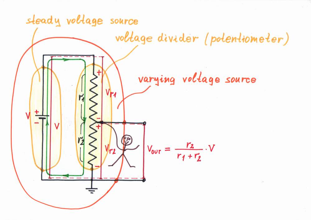
In nature, real power sources (beings, machines etc.) are limited. Only, when they are not loaded they behave perfectly. Mechanical analogy: an empty car moves easily with high rate of movement. Water analogy: the water pressure inside the piping is high. Human analogy: people (friends, husbands, parents etc.) are perfect when there aren't problems to solve.
Starting point: Making a simple varying voltage source (unloaded)
By the way, can we build a varying voltage source by connecting a varying resistor (a rheostat) after a steady voltage source?
top < prev step - 1 - 2 - 3 - 4 - 5 - 6 - 7 - next step > end
Problem. In nature, when the real power sources (beings, machines etc.) are loaded they droop. Mechanical analogies: if we have to raise a big weight, we droop; if we load a car, it decreases its rate of movement. Water analogy: if we open the faucet, the water pressure inside the piping falls. Human analogies: if problems arise, people droop (friends - when we need help, husbands - when their wives spend too much money, parents - when more childs were born etc.)
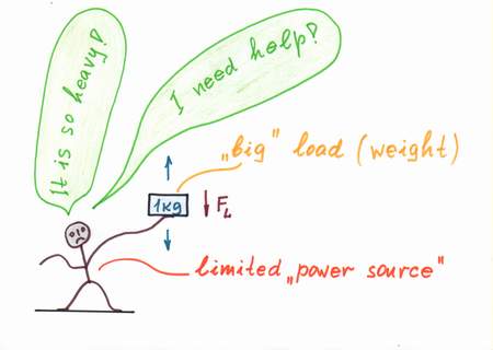
Problem: Simple varying voltage source loaded
A similar problem exists in electronics (electricity) when imperfect voltage sources are loaded. In our case, if we connect a load RL, it sucks a current IL and the output voltage VOUT drops (another explanation: the lower leg of the voltage divider has lower resistance r2||RL). The classic solution is to connect an op-amp voltage follower before the load, in order to decrease the current IL (to increase the load resistance RL). Unfortunately, this remedy introduces some errors inherent for this circuit.
top < prev step - 1 - 2 - 3 - 4 - 5 - 6 - 7 - next step > end
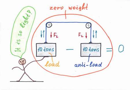
Remedy. What can we do in real life when some object (being, machine etc.) supplied by a real power source droops? We can just help it. For this purpose, we usually use an additional power source, which "helps" the main source by compensating the losses caused by the load.
Mechanical analogy: if a lift has to raise a heavy loaded cage, we can help it by an equivalent "anti-weght". Water analogy: if the water pressure inside the piping falls, we may connect an additional water pump to raise the pressure. Human analogy: if a loaded husband droops, a lover appears to help him in serving the wife:) As a result of the helping, the objects have the feeling that the loads are disappeared: a small boy can raise tons of weight, a "helped" husband is happy as his wife doesn't spend so much money yet, etc.
What a wonderful trick it is - just add an additional power source in parallel with the imperfect source and make its "flow rate" equal to the rate consumed by the load!
Remedy: "Helping" the imperfect voltage source
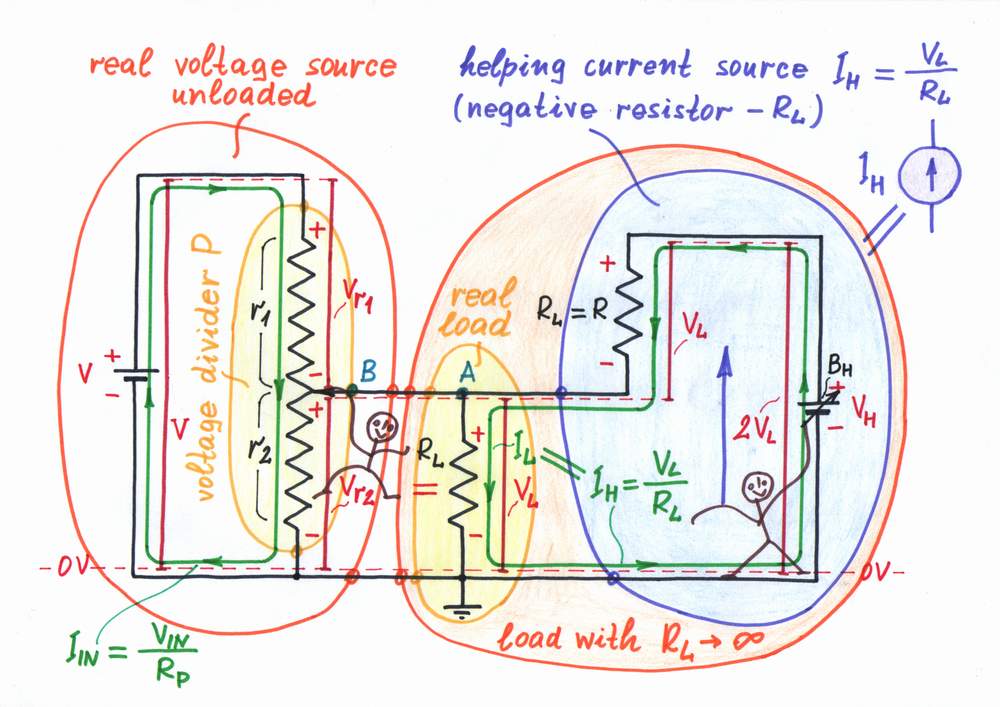
Since this idea is so powerful, let's try to implement it into our circuit. Obviously, as the load "pulls" the point A down toward the ground we have to put something to "pull" the point A up with ah equivalent "force". In terms of elecricity, that means to connect an additional varying voltage source BH through a pull-up resistor R = RL to the point A. Well, let's do it.
I will control the voltage source BH so that it produces two times higher voltage than the load voltage VL. For this purpose, I will connect a voltmeter across the load to measure the voltage VL and will keep VH = 2VL. As a result, the voltage source BH makes a current IH = (VH - VL)/R = (2VL - VL)/RL = VL/RL = IL flow through the load. Actually, BH and R constitute a "helping" current source IH (a negative resistor -RL) connected in parallel to the load.
Wonderful! Now, the whole load current IL is provided by the "helping" current source IH (the negative resistor -RL) instead by the main voltage source V. The load does not consume any energy from the main voltage source since it is supplied completely by the "helping" source.
Have you noticed that there is a striking resemblance between the mechanical and electrical versions? This will help us to understand completely the phenomenon. Look again at the circuit diagram above and imagine that the load "pulls" the point A down toward the ground while the resistor R "pulls" the point A up toward the voltage VH. As a result of this "stretching", the point A "experiences" weightlessness (as it pulls itself up) and it follows easily the point B. There is no current flowing between the point B and point A since the whole right part of the circuit (RL, R and VH) behaves as a load with infinite internal resistance. In circuitry, they call this eccentric trick with the strange name bootstrapping. Only, Baron Munchhausen has invented it about two centuries ago: the legend says that he was using his own boot straps to pull himself out of the sea:).
top < prev step - 1 - 2 - 3 - 4 - 5 - 6 - 7 - next step > end
In the electrical circuit above, I have controlled manually the "helping" voltage source BH so that it was producing two times higher voltage than the load voltage. Only, I have got bored of doing this donkeywork:); so, let's try to make some electronic device do it...
Implementation. It seems that a non-inverting amplifier A having a gain of (only) +2 will work perfectly. We have just to connect the amp's input to the point A and the amp's output in place of the "helping" voltage source BH. The amplifier is single-supplied since here the input voltage is only positive.
Operation. The amplifier doses the voltage +V of the power supply, in order to produce the voltage needed (VA = 2VR). Actually, the steady voltage source +V and the amplifier A constitute the varying voltage source needed:
Steady voltage source + amplifier = varying voltage source
The combination of this composed voltage source and the resistor R acts as a "helping" current source. It injects a current IH through the resistor R into the point A and raises its voltage; as a result, the point A "pulls itself up". The output voltage affects the input voltage as a part of the output voltage adds to the input voltage. This great phenomenon is referred to as positive feedback.
What do you think? Can this connection cause a problem with the stability (will the amplifier saturate)? A tip: calculate the gain through the feedback loop and check if it is smaller than 1. If yes, there is no problem. Why?
Circuit implementation: Making a negative resistor
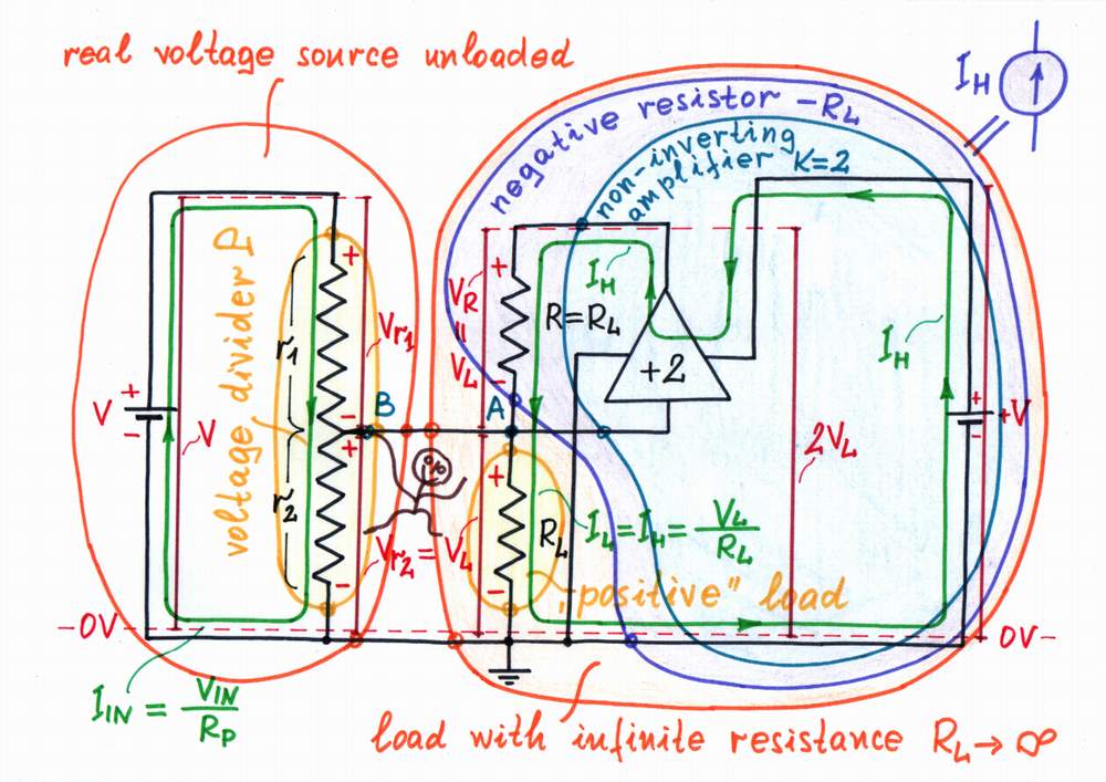
The combination of a power supply +V, a non-inverting amplifier A with gain A = +2 and a resistor R acts as a "helping" current source. The circuit is stable because RL||r2/(RL||r2 + R).A < 1.
top < prev step - 1 - 2 - 3 - 4 - 5 - 6 - 7 - next step > end
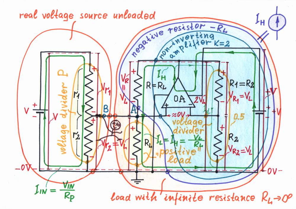
In electronics, there are perfect operational amplifiers having extremely large but unstable voltage gain (typically 200000). By applying a negative feedback we can make an op-amp amplify exactly two times needed. How do we do this magic?
Negative feedback systems have a nice feature to reverse the causality in electronic circuits (we will scrutinize this phenomenon later in the circuit stories about negative feedback). For example, if we put a passive circuit (an integrator, differentiator, attenuator, etc.) into the feedback loop, we will obtain the opposite active circuit (a differentiator, integrator, amplifier, etc.)
According to this idea, let's build a voltage divider having a ratio 0.5 by connecting in series two equal resistors R1 and R2; then, let's connect it between the op-amp's output and the inverting input. As a result, we obtain an op-amp non-inverting amplifier having the stable gain of 2 needed.
If we put a voltage divider with a ratio of 1/K into the op-amp's negative feedback, we obtain an op-amp amplifier having a gain K.
We may say that this circuit is a negative impedance converter since the "positive" resistor R is converted into negative one -R.
Op-amp implementation: Making an NIC
Circuit operation
When we apply the positive input voltage V to the voltage divider P an output voltage drop Vr2 = VL appears. The load begins immediately "pulling" the point A down toward the ground. Only, the op-amp "notes" the positive voltage difference between the two inputs and begins increasing its output voltage VOA. For this purpose, it "pushes" a current IH through the resistor R (connected between the output and the non-inverting input) and a current Id through the resistor R1 (connected between the output and the inverting input). It is comparing continuously the voltage drops across the two resistors and stops when it manages to zero the voltage difference between the inputs (VL - 0.5VOA = 0). At this moment, the output voltage is exactly as much as needed (VOA = 2VL).
Maybe, you have noted that there are two feedbacks (negative and positive) in this odd circuit. Can this connection cause a problem with the stability?
You may think that the resistors constitute two voltage dividers or an unbalanced Wheatstone bridge. The positive feedback returns a voltage V(+) = RL||r2/(RL||r2 + R) < 0.5VOA by the left divider to the non-inverting input; the negative feedback returns higher voltage V(-) = R2/(R1 + R2) = 0.5VOA by the right divider to the inverting input. As a result, the negative feedback dominates; so, the circuit is stable.
More figuratively speaking, the op-amp "pulls" the two inputs up simultaneously but the inverting input more vigorously than the non-inverting one. As a result, it manages to reach an equilibrium.
top < prev step - 1 - 2 - 3 - 4 - 5 - 6 - 7 - next step > end
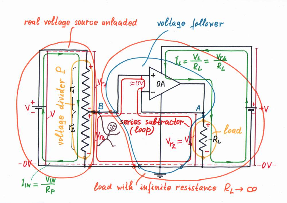
A more classical solution of the problem discussed is to connect an op-amp voltage follower before the load, in order to decrease the current IL (to increase the load resistance RL). Then, what is the difference between the two circuits? What circuit is better?
Voltage follower. In this arrangement, the load is completely detached from the real voltage source by the high input resistance of the voltage follower (it stays between the source and the load). The op-amp passes the whole current IL needed through the load (the current is caused by the power supply +V). For this purpose, it compares continuously the voltage drop VL across the load with the output voltage Vr2 of the voltage divider and changes the load current IL so that there isn't any difference between the two voltages. As a result, the op-amp compensates the load resistance even when it varies. Only, a small voltage difference ever exists because of the finite op-amp gain.
Negative resistor. In this arrangement, the load is not detached from the real voltage source; the negative resistor (NIC) is just connected in parallel to the load. The op-amp produces the whole load current IL needed and pushes it through the load. For this purpose, it creates a "mirror" load voltage VL and applies it across a "copy" load resistance R = RL instead across the "original" load resistance RL (it "supposes" that the two resistances are equal). But what happens, if the "original" load resistance varies? The op-amp will be misled and an error will appear. Only, if we make the "copy" resistance a little smaller (or a "mirror" voltage - a little higher) than needed, it is possible to compensate the small static error due to the finite op-amp gain.
Comparison with the classical solution
In a voltage follower arrangement, the op-amp compensates the load resistance even when it varies. Only, a small voltage difference ever exists because of the finite op-amp gain.
In an NIC arrangement, if we make the NIC over-compensate the load resistance, it is possible to eliminate the small static error.
top < prev step - 1 - 2 - 3 - 4 - 5 - 6 - 7 - next step > end
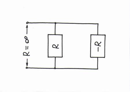
Warning: this is only a humor! Don't you think that all these explanations, analogies, voltage bars and diagrams, current loops etc. are unnecessary:)? Instead, especially if we are teachers who don't like to waste our time in explaining circuit phenomena to students (I know such teachers), we can just say, "Connect in parallel with the positive resistor R a negative resistor -R, in order to get infinite resistance (-R||R = ∞)."
How simple and clear it sounds! How convenient for lecturers it is! But how nonundestandable for students it is! Even, if we back up this formal speculation with all kinds of formulas, it will remain nonunderstandable because the basic idea of the phenomenon is hidden!
I hope you don't do that! If you think so, I will be glad to get in touch with you.
Formal explanation (if we only were bad teachers...)
circuit-fantasia > circuit stories > inventing circuits > parallel resistive losses compensation
Last updated April 7, 2007