 Inventing Circuits on the Whiteboard...
How do We Make Decreased, Zero and Negative Differential Resistance?
In electronics, there are mysterious two-terminal electronic components having negative differential resistance. Some of them (e.g. tunnel and Gunn diodes) have the so-called N-shaped IV curve while other components (e.g. neon lamps, thyristors) have an S-shaped IV curve.
From many years, I have been asking myself, "How does such a negative differential resistor actually work?", "What does such an electronic component actually do in the region of negative resistance?" etc. Finally, I realized that, in order to grasp the basic idea behind the so strange electronic devices, I had to place myself in their place and to begin performing their functions. I realize that it sounds strange but yet I continue claiming: The only way for a human being to understand really how such an abstract electronic device works is to simulate its behavior!
We know that the the truth about circuit phenomena is hidden rather in the movement from simple to complex circuits than in the final perfect circuit solutions. So, the best way to reveal the negative resistance phenomenon is to show the evolution of "ordinary" ohmic resistor into negative one. In this story, I will reveal the secret of S-shaped resistors by following the succession: ohmic > decreased > zero > negative differential resistance.
The key of understanding negative differential resistors is to think of them as dynamic resistors with varying ohmic resistance. In our routine, we may observe this phenomenon in situations where we experience a varying impediment when we implement our purposes. In these cases, someone/something decreases dynamically his/her/its resistance so that we have the feeling that the resistance is decreased. This dynamic "helper" may aid us in three degrees (under-, exactly- or over-). S-shaped negative resistors represent the last degree when someone "over-helps" us. Similarly, in electrical circuit, a current may flow through components having ohmic, decreased, zero or negative differential resistance.
Internal links (from this page):
1. Starting point: Static ohmic resistance
2. Investigating the ordinary ohmic resistance
3. Decreasing the resistance by varying the resistance slightly
4. Decreasing the resistance by varying the resistance exactly
5. Obtaining a negative resistance by varying the resistance considerably
Other links from this site:
A heuristic approach to teaching negative resistance phenomenon * NEW *
How do we create dynamic resistance?
External links:
Wikipedia: Ohmic device, Resistor, Negative resistance
Another fresh viewpoint at negative resistance,
What is the basic idea behind negative impedance converter (NIC)?
Color key:
Links: this page, other my pages, external, multimedia, handmade.
Text: analogies, conclusions.
top < prev step - 1 - 2 - 3 - 4 - 5 - next step > end
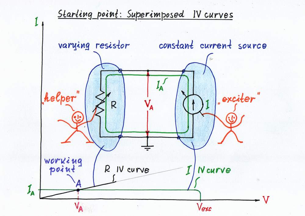
As we know from our routine, we usually experience a steady impediment (resistance) when we implement our purposes. Similarly, in electricity we usually deal with ordinary ohmic resistors having a steady resistance, which does not depend on the voltage across them and also on the current passing through them. As an example, let's consider a possibly simplest circuit consisting of only two 2-terminal components: a constant current source IIN acting as an input source and a varying ohmic resistor R (rheostat) acting as a load. In this arrangement, you may control the input current source while I will control the rheostat; shortly, you are the source, I am the load:) If you agree, let's start the game!
Initial position. In the beginning, I set the rheostat's slider in some position according to current resistance R; you set some input current IA. As a result, a voltage VA appears across the resistor R.
In order to present graphically the circuit operation, let's superimpose the two IV curves (of the source and of the load) on the same coordinate system. In this arrangement, the intersection point A (the working point or quiescent point here) represents the current (local) magnitudes of the current IA and the voltage VA.
Starting point: Static (ohmic) resistance
top < prev step - 1 - 2 - 3 - 4 - 5 - next step > end
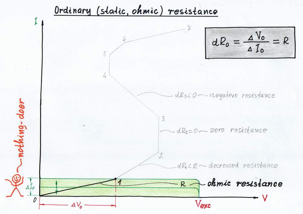
When we encounter a constant impediment, the output quantity is proportional to the input one. A water analogy: if you increase the water stream, the water pressure increases accordingly to the faucet position.
Let's now investigate this phenomenon in our circuit. For this purpose, first connect a voltmeter across the resistor R and an ammeter in series with it. Then, you begin increasing gradually the input current IIN; I will do... nothing:)
According to Ohm's law, the voltage across the resistor is proportional to the current passing through it (V = R.I). On the graphical representation, when you vary the current IIN of the input current source, its (your) IV curve moves vertically. As a result, the working point A slides over the IV curve of the ohmic resistor R from point 0 to point 1.
The slope of R IV curve represents graphically the ohmic resistance R. It is a "static" resistance as it does not depend on the location of the working point A.
Investigating the ordinary ohmic resistance
top < prev step - 1 - 2 - 3 - 4 - 5 - next step > end
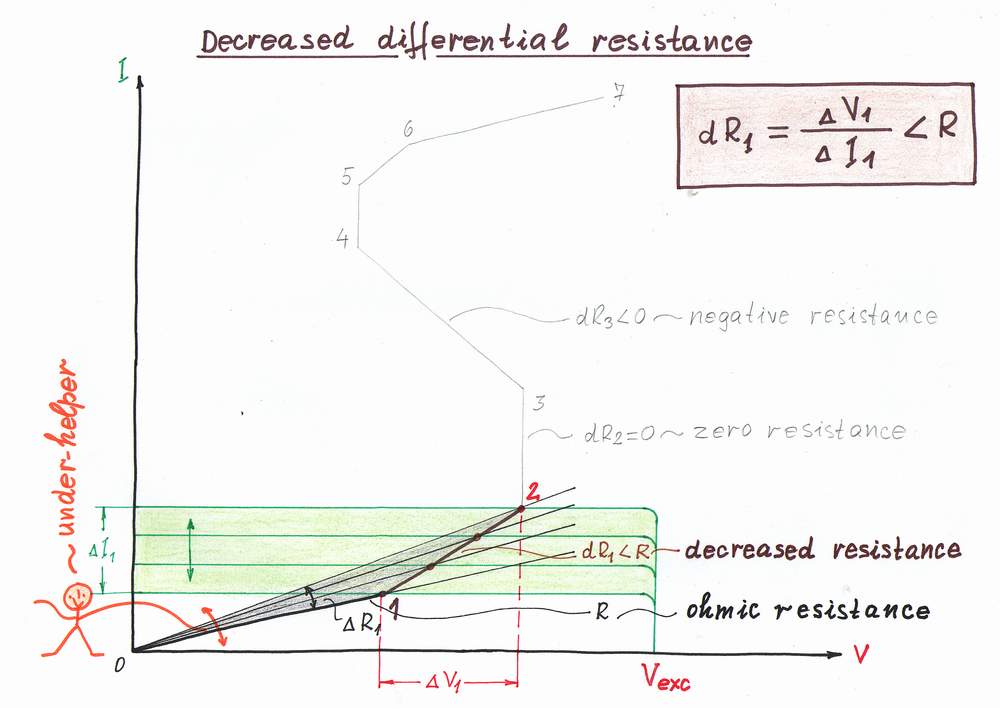
There are many situations in our life when someone helps us by changing (inconspicuously for us) the impediment. As a result, we experience a smaller resistance when we implement our purposes. A water analogy: If I begin opening gradually the faucet when you increase the water stream, the water pressure will increase lazier and you will have the feeling that the water resistance is decreased.
Let's apply this trick to decrease the resistance R in our circuit. When you reach the point 1, I decide to begin helping you (I don't know why, maybe because I lke you:). For this purpose, I begin moving slightly the slider thus decreasing gradually the ohmic resistance R. As a result, you have the illusion that the resistance R has decreased; you see a new, decreased dynamic resistance dR < R. Actually, I have dynamized the "static" resistance R converting it into a smaller differential resistance dR.
On the picture, when you increase the input current IIN from point 1 to point 2, its IV curve moves upward remaining parallel to itself. But now, as I decrease the resistance R at the same time, its IV curve rotates contraclockwise. As a result, the working point A slides from left to right over a new more vertical IV curve, which represents the new dynamic resistance dR < R.
Decreasing the resistance by varying the resistance slightly
top < prev step - 1 - 2 - 3 - 4 - 5 - next step > end
Now imagine that the "helping" idea above is improved so that someone changes (inconspicuously for us) the impediment to such extent that we do not experience any resistance when we implement our purposes. An analogy: If I begin opening considerably enough the faucet when you increase the water stream, the water pressure will stay constant. In this way, I will act as a constant pressure regulator.
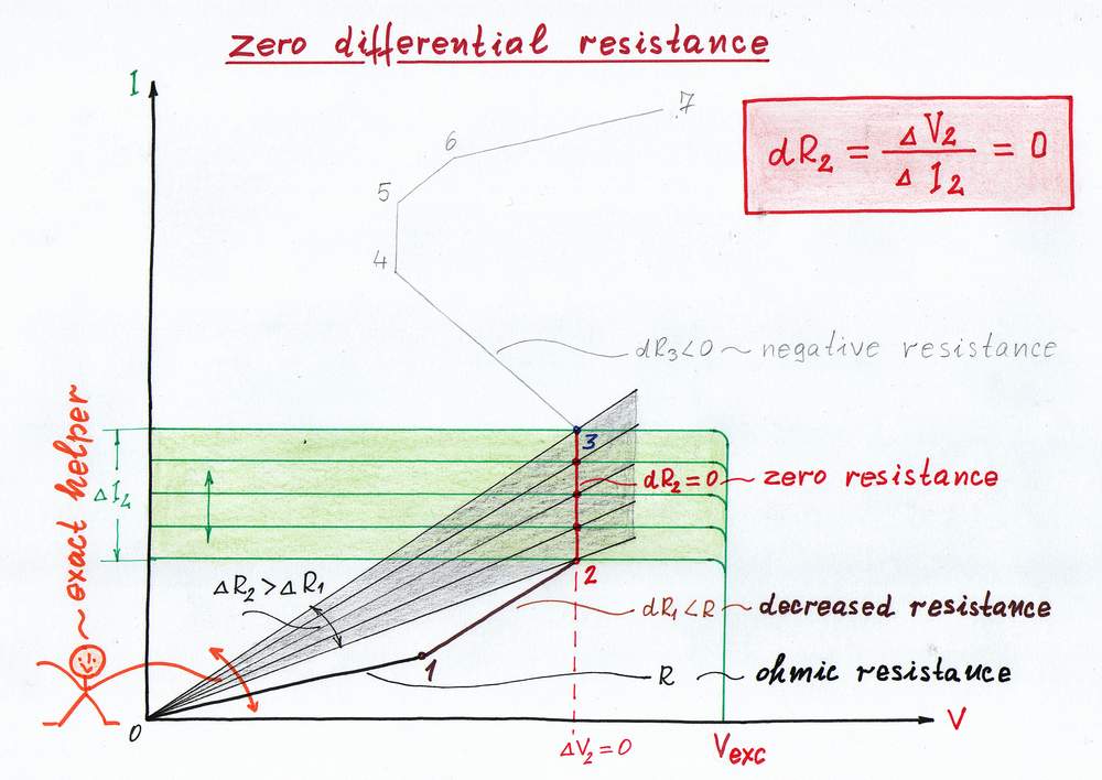
Let's apply this trick to zero the resistance R in the circuit. When you reach the point 2, I begin moving vigorously enough the slider thus decreasing considerably the ohmic resistance R. As a result, you have the illusion that the resistance R has disappeared; you see new, zero differential resistance dR = 0.
On the graphical presentation, when you increase the input current IIN from point 2 to point 3, its IV curve moves upward as before. Now, I decrease vigorously enough the resistance R at the same time; so, its IV curve rotates rapidly enough contraclockwise. As a result, the working point A slides upward from point 2 to point 3 over the vertical IV curve of the new dynamic resistance dR = 0. In electronics, all kinds of diodes and other voltage-stable components act in this way.
Zeroing the resistance by varying the resistance exactly
top < prev step - 1 - 2 - 3 - 4 - 5 - next step > end
Finally, imagine that the "helping" idea is enormously improved so that our helper goes too far decreasing many times more the impediment than we actually need. An analogy: If I begin opening the faucet very much when you increase the water stream, the water pressure will even decrease.
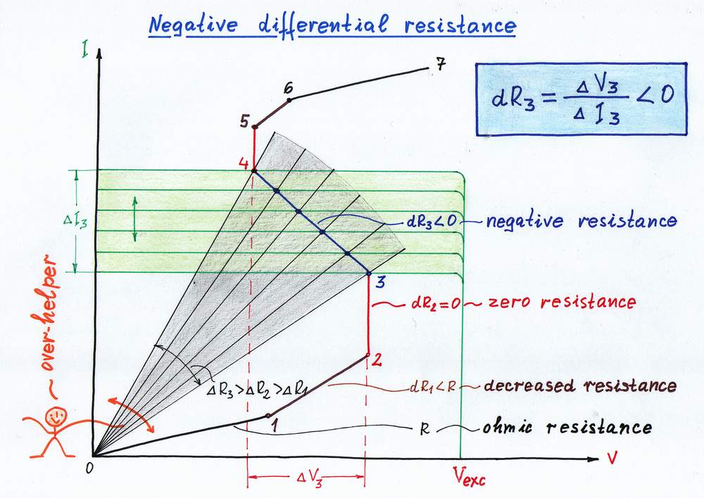
If I put this idea in practice, I will convert the ordinary "positive" resistance R into a negative differential resistance. Well, let's do it. When you reach the point 3, I begin moving extremely vigorously the slider thus decreasing enormously the ohmic resistance R. As a result, you have the illusion that there isn't any resistance; instead, you will think that there is a source connected in the circuit.
Let's finally see the graphical presentation according to this great idea. Again, when you increase the input current IIN from point 3 to point 4, its IV curve moves upward as usual. But now, as I decrease extremely vigorously the resistance R at the same time, its IV curve rotates enormously rapidly contraclockwise. As a result, the working point A slides upward from point 3 to point 4 over the vertical IV curve of the new negative differential resistance dR < 0. In electronics, thyristors and neon bulbs act in this way (in certain parts of their IV curves).
Negative resistance, Another fresh viewpoint at negative resistance
Obtaining negative resistance by varying the resistance considerably
 :
:
circuit-fantasia > circuit stories > inventing circuits > s-negative differential resistance
Last updated June 10, 2007