 Inventing Circuits on the Whiteboard...
Passive Voltage-to-Current Converter
Have you noted that, in low-voltage electronics, the electrical attributes voltage and current cary mostly information rather than energy? And, for some reasons, we prefer voltage as a data carrier? As a result, the most electronic circuits have voltage inputs and outputs.
Unfortunately:), there are also current-input and current-output devices. Examples: an ammeter has only a current input, a current source has only a current output, a bipolar transistor has a current input and a current output, a tube and an FET transistor have a voltage input and a current output, a transimpedance amplifier and a Norton amplifier have a current input and a voltage output, etc. In these cases, we need devices converting the electric attributes carrying information from voltage to current and v.v.
In this story, we begin revealing the secret of the famous (so much as Ohm's law) voltage-to-current converter , which changes the electrical data carrier from voltage to current. As usual, there are two versions of this circuit - passive ("bad") and active ("good"); here, we begin with the "bad" passive version. Then, in another story dedicated to the "good" active version, we will show that there is a close interrelation between the two circuits: the active version is come from the passive one (the active version comprises the passive one, it is just an improved passive version). In this way, we will show the evolution of the famous circuit moving, step-by-step, from simple to complex.
Internal links:
1. Non-electrical domain: Pressure causes flow
2. Electrical domain: Voltage causes current
3. Exploring the circuit operation in an attractive manner
4. V-to-I converter acting as an output device
5. V-to-I converter acting as an input device
6. What are the input/output resistances?
7. What are the imperfections of the passive version?
8. Can we improve the imperfect passive circuit?
Color key
Links: this page, other my pages, external, multimedia, handmade.
Text: analogies, conclusions.
The basic idea behind the circuit
top < prev step - 1 - 2 - 3 - 4 - 5 - 6 - 7 - 8 - next step > end
Non-electrical domain : Pressure causes flow
Have you ever asked yourself questions about causality in our world: "Which came first, the egg or the hen?" (troubling philosophers from the remote past to the present day:), "What causes what - pressure causes flow or flow causes pressure?" etc. As it is hard for us to answer this primary questions we might just assume that both the alternative answers are possible.
Well, let's first begin with the more popular assumption that pressure causes flow. Really, in life, we may observe many situations where a pressure-like quantity puts in motion a flow-like one through an impediment. Here are some examples.
Pneumatic. Imagine a constant pressure pump moving air through a closed loop of pipes (we may carry out such a funny experiment by using an old-fashioned air cleaner, which sucks and blows air through a closed loop made from a corrugated hose).
Water. Remember famous communicating vessels where the height difference between the two vessels cause water to flow.
Thermal. If we warm up a metal bar on the one side, heat begins flowing to the other side.
Mechanical: imagine that a motor drives a belt; energy is flowing along this "circuit".
Informational: someone tells a story to somebody else - data flows through the phone line.
Money: the rich give money to the poor etc.
Other examples: just look around and you will find a lot of pressure-causes-flow analogies.
Conclusion. If we apply a pressure to an impediment, a flow begins flowing. In this arrangement, the pressure-like, flow-like and impediment-like attributes are interrelated. Usually, the output flow-like variable is proportional to the input pressure-like one:
In order to establish a current, a pressure has to be applied across an impediment.
The impediment can convert the pressure-like variable into a flow-like one.
Building a simple passive circuit
top < prev step - 1 - 2 - 3 - 4 - 5 - 6 - 7 - 8 - next step > end
In electricity, we might asked ourselves the electrical version of the questions above, "What causes what in Ohm's law - voltage causes current or current causes voltage?" Again, as it is hard to answer this primary question we might assume that both the alternative answers are possible.
In this story, we will begin with the more popular assumption that voltage causes current in the most elementary Ohm's circuit. That means that it is supplied by a voltage source. Simply speaking, if we apply a voltage VIN across a resistor R, a proportional current IOUT = VIN/R begins flowing through the circuit. We may say that this is a voltage-causes-current formulation of Ohm's law:
I = V/R
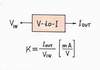
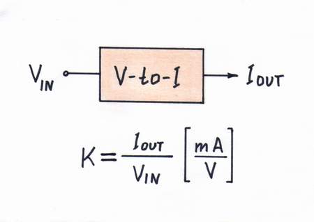
In this voltage-supplied circuit, the resistor R determines the current flowing through it. We usually say that the resistor converts the voltage VIN into a proportional current IOUT or it serves as a simple voltage-to-current converter - a linear circuit with transfer ratio k = IOUT/VIN [mA/V].
A bare resistor can convert voltage into current.
Electrical domain : Voltage causes current
![In this voltage-supplied circuit, the resistor R determines the current flowing through it thus converting the voltage VIN into a proportional current IOUT. In this way, the resistor R serves as a voltage-to-current converter - a linear circuit with transfer ratio k = IOUT/VIN [mA/V]. Click to view full-size picture.](building_v-to-i_1000.jpg)
Exploring the circuit operation in a more attractive manner...
top < prev step - 1 - 2 - 3 - 4 - 5 - 6 - 7 - 8 - next step > end
Circuit operation. We may present the circuit operation and Ohm's law in a more attractive manner than I = V/R, if we visualize the invisible electrical quantities by means of voltage bars and current loops (see the circuit diagram above). They are based on the famous water tower and fish tank hydraulic analogies. In this "geometrical" presentation, the height of the voltage bars is proportional to the corresponding voltages (drops) and the thickness of the current loop is proportional to the magnitude of the current (see also an interactive animation).
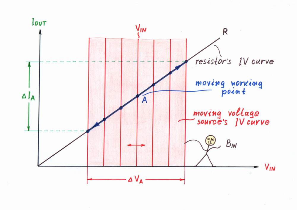
Then, we may present the circuit operation (and Ohm's law) graphoanalytically (see the picture on the right). As the voltage across and the current through the two 2-terminal components (the voltage source and the resistor) are the same, we may superimpose their IV curves on a common coordinate system. The intersection of the two lines is the operating point A; it represents the current magnitudes of the voltage VA and the current IA.
When we vary the voltage VIN of the input voltage source, its IV curve moves horizontally (see also an interactive animation). As a result, the working point A slides over the IV curve of the resistor R; its slope represents the converter's ratio.
...by superimposed IV curves
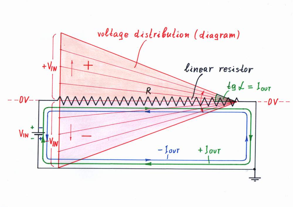
Finally, we may use another attractive graphical interpretation of Ohm's law - the voltage diagram (the voltage distribution along the resistive film inside a linear resistor). In this geometrical presentation, each local voltage drop is represented by a local bar with corresponding height (for simplicity, only the envelope of the voltage diagram is drawn).
We may intuitively derive the idea of voltage diagram from many examples of our human routine: hydraulic, pneumatic, mechanical, thermal, etc. These analogies help to understand that the local voltages along the resistive film decrease gradually (linearly) from the left to the right when the input voltage varies.
Actually, this arrangement reproduces the famous Ohm's experiment (see also another interactive animation ). In this arrangement, the angle α represents the current IOUT.
...by a voltage diagram
Applications: V-to-I converter acting as an output device
top < prev step - 1 - 2 - 3 - 4 - 5 - 6 - 7 - 8 - next step > end
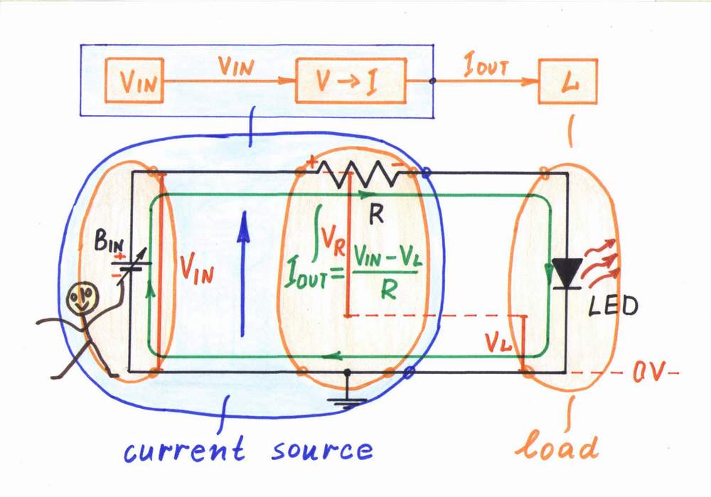
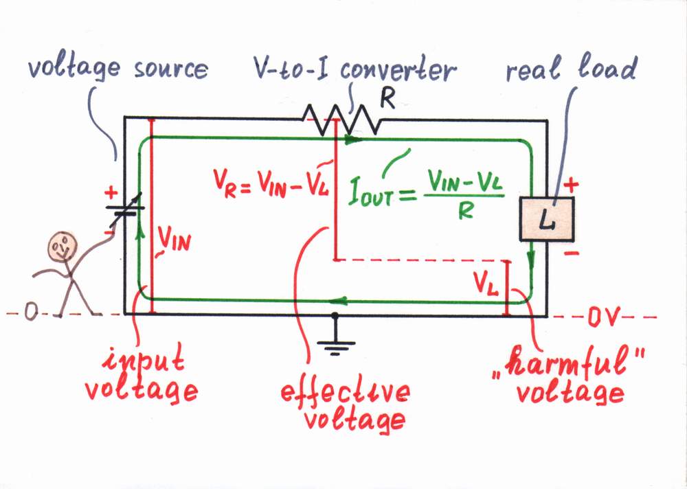
Voltage-controlled current source. Almost all the natural electrical sources are constant voltage sources (primary and secondary batteries). Actually, there are not constant current sources in nature (excepting inductor, Van der Graaf generator and photodiode); so, if we need a current source, we have to build it (see the phulisophy). For this purpose, we connect a voltage-to-current converter (a resistor R) in series with the input voltage source VIN. The building formula is:
Current source = Voltage source + Voltage-to-current converter
If we shorten the circuit output with an ideal current load (just a piece of wire), it will generate a constant current IOUT = VIN/R.
A real load (an LED on the figure) introduces some voltage drop VL, which affects the excitation voltage VIN. Now, the voltage difference VIN - VL determines the current IOUT instead the voltage VIN; as a result, the current decreases (see imperfections).
Voltage-controlled current source
Applications: V-to-I converter acting as an input device
top < prev step - 1 - 2 - 3 - 4 - 5 - 6 - 7 - 8 - next step > end
Compound voltmeter. A meter movement (a galvanometer) is actually an ammeter. In order to measure a voltage by an ammeter, we connect a voltage-to-current converter (the so called "multiplier" resistor R) before the ammeter. In this way, we may present the classic voltmeter as a composed device consisting of two components:
Compound voltmeter = Voltage-to-current converter + Ammeter
The multiplier resistor of a classic voltmeter acts as a voltage-to-current converter.
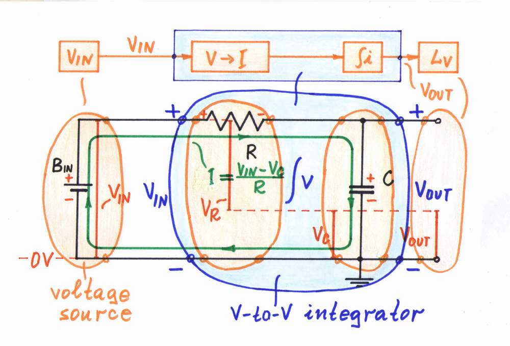
Compound passive converters: Similarly, in the popular passive circuits of capacitive integrator, inductive differentiator, logarithmic converter, etc., the resistor acts as a voltage-to-current converter:
V-to-V RC integrator = V-to-I converter + I-to-V C integrator
V-to-V RL differentiator = V-to-I converter + I-to-V L differentiator
V-to-V RD log converter = V-to-I converter + I-to-V D log converter
In these circuits, the respective I-to-V converters introduce some voltage drop, which affects the excitation voltage VIN. As a result, the current decreases and an error appears (see imperfections).
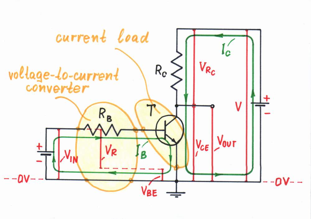
Transistor base resistor. A BJ transistor is a current-controlled device; it actually "shorts" the input source (more precisely speaking, we may drive the transistor by a small voltage VIN < VBE0). In order to drive a transistor by a relatively high voltage (for example, in the circuit of a transistor switch), we connect a base resistor in series with the base-emitter junction. It acts as a voltage-to-current converter thus endowing the transistor with a voltage input:
Voltage-input transistor = V-to-I converter + current-input transistor
With the same purpose, resistors are connected to the inverting and non-inverting inputs of a Norton op-amp to apply a voltage.
The transistor's base resistor acts as a voltage-to-current converter.
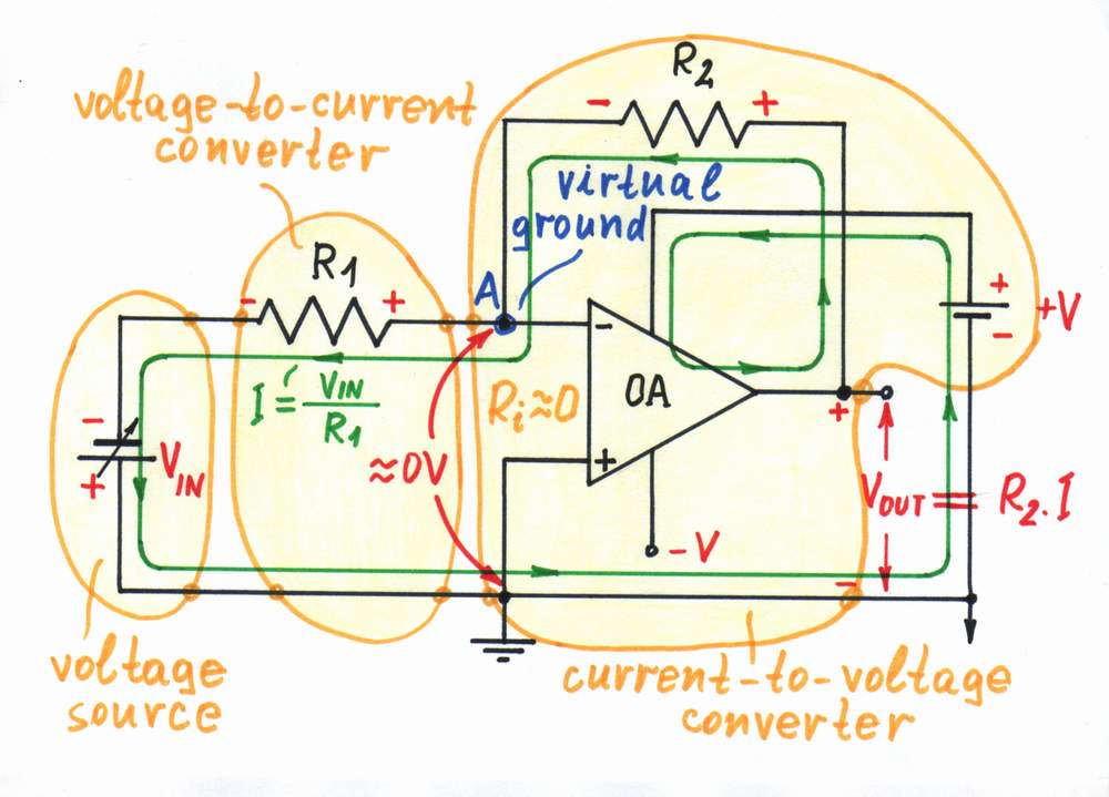
Op-amp inverting amplifier (an input part). In the op-amp inverting circuits the op-amp keeps the voltage of the inverting input at zero level (the so-called virtual ground). As a result, the circuit behaves as a current-controlled device, which "shorts" the input source connected to the inverting input. In order to drive the op-amp by a voltage (for example, in the circuit of an op-amp inverting amplifier), we connect a resistor acting as a voltage-to-current converter between the input voltage source and the inverting input (Fig. 9):
Op-amp inverting amplifier = V-to-I converter + op-amp I-to-V converter
Op-amp V-to-V RC integrator = V-to-I converter + op-amp I-to-V C integrator
Op-amp V-to-V RL differentiator = V-to-I converter + op-amp I-to-V L differentiator
Op-amp V-to-V RD log converter = V-to-I converter + op-amp I-to-V D log converter
What are the input/output resistances?
top < prev step - 1 - 2 - 3 - 4 - 5 - 6 - 7 - 8 - next step > end
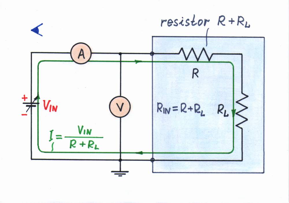
It is interesting to investigate the input and output resistance. For concreteness, let us assume a resistive load RL.
What is the input resistance?
First, connect an ammeter in series with and a voltmeter in parallel to the converter's input; then vary the input voltage to investigate the input resistance. Looking from the side of the input source we see two resistors connected in series; so, the input resistance is RIN = R + RL. As you can see, it depends on the load resistance RL.
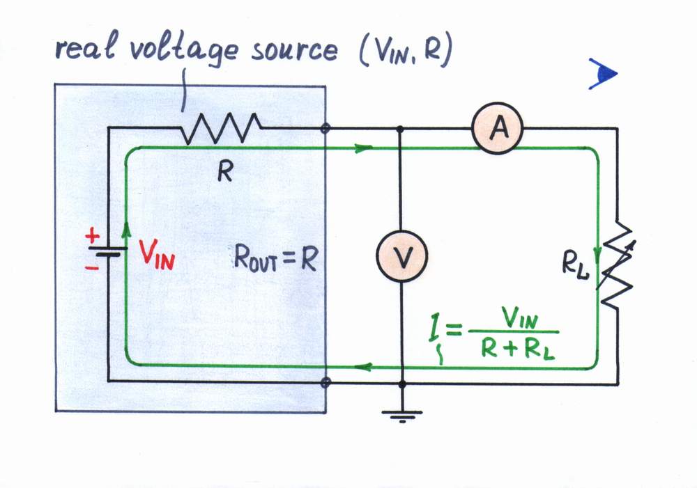
What is the output resistance?
Now, connect a voltmeter in parallel to and an ammeter in series with the converter's output; then, vary the load resistance (voltage) and observe the current to investigate the output resistance. Looking from the side of the load, we see only the resistor R; so, the output resistance is ROUT = R. Here we suppose that the input voltage source is perfect (i.e., it has zero internal resistance).
Imperfections
top < prev step - 1 - 2 - 3 - 4 - 5 - 6 - 7 - 8 - next step > end
Real loads act as imperfect current loads dissipating energy (for example, simple ammeter, current measuring resistor, a diode, etc.) or storing energy (a capacitor, secondary battery, an inductor, etc.) They have some resistance (liner or non-linear), capacitance or inductance, which cause a voltage drop VL to appear across the load). As a result, now the voltage difference VIN - VL determines the current IOUT instead only the voltage VIN; as a result, the current decreases. You can explore the circuit operation in a more attractive way, if you click Exploring button in the interactive flash movie or if you go to Stage 2 in the interactive flash builder.
The same problem exists in the water analogy of communicating vessels, where the height difference between the vessels determines the flow rate instead only the height of the input water pressure source to determine it.
Improvement
top < prev step - 1 - 2 - 3 - 4 - 5 - 6 - 7 - 8 - next step > end
Classic remedy. In some cases (e.g., when the passive voltage-to-current converter is a part of a current source), we may apply a paradoxical trick from our humane routine - depreciate a harmful quantity by another many times bigger harmful quantity. In electricity, this is the well-known classic remedy to decrease the error caused by the load: increase both the excitation voltage V and the resistance R to suppress the load voltage drop VL. As a result, the output current remains the same but the influence of the load (even, if it varies) decreases; thus we get a comparatively constant current source. If we go too far, we will "invent" the classic "electricity" definition of the ideal current source, where an infinite voltage divided by an infinite resistance gives a finite current. For example, imagine that we build 1mA current source first by using 10V voltage source and 10K resistor, then - 100V and 100K, after - 1000V and 1000K, ...and finally - infinite V and infinite K. Only, imagine what power the resistor will dissipate in this compromised solution! In addition, we usually can not change the input voltage V and the resistance R. How to solve the problem then?
Looking for a perfect remedy. Note, that a strange contradiction exists in the simple voltage-to-current converter: from one side, the voltage drop V L is useful as it serves as an output voltage; from the other side, this voltage drop is harmful as it decreases the actual current-creating voltage VR across the resistor R. How can we solve this contradiction? Remember what we do in life when something bad appears.
If you do not manage to find a remedy, visit the pages below; they might suggest how to figure out the problem.
How do we create a virtual ground?
Inverting op-amp RC integrator
Inverting op-amp current source
Wikibooks: Circuit idea - Op-amp inverting voltage-to-current converter
Links to related web resources
Elementary passive converters with current output is a teacher's story about the simplest electric converters (from the exercices with my students, 2004).
Reinventing the constant current source reveals the philosophy of the constant current sources.
Op-amp circuit builder shows how to transform any passive converter into an active one (choose the resistor R2 from the library on the right side).
Wikibooks: Circuit idea - Passive voltage-to-current converter reveals the idea behind the circuit.
Wikipedia: Voltage-to-current converter builds consecutively the passive and active versions of the voltage-to-current converter.
Current-to-voltage converter is dedicated to the passive and active versions of the inverse current-to-voltage converter.
Resistors and Transistors show how a base resistor can act as a simple voltage-to-current converter (well illustrated and animated).
Voltmeter design presents a classic but useful viewpoint at the ordinary "movement" voltmeter.
An analogy for Ohm's Law presents the famous fluid analogy of an electric circuit.
circuit idea - circuit-fantasia > circuit stories > inventing circuits > passive voltage-to-current converter
Last updated July 14, 2007