 and regulating element.
7.1.1. Emitter (source) follower unloaded. Building the circuit by using the block diagram. Visualizing the operation by a potential diagram. Discussion: What does act as a comparator in the circuit of the emitter follower?
home - bg - intro - contents - library - resources - feedback - digital
Class Exercise 7 (April 26 - May 1, 2004)
7. Transistor Circuits with Feedback
So far, we have managed to put a total of 52 circuit building blocks into our library . Today, using the powerful negative feedback principle, we will improve the transistor circuits from our last meeting. Thus, we will enrich the library with a further 7 building blocks; so, it will grow to 59 basic circuits:
| Followers | emitter follower | emitter follower disturbed |
| Transistor amplifiers (deliberately disturbed followers) with NFB, controlled from the: | ||
| base | emitter | both base and emitter |
| common emitter stage | common base stage | differential amplifier |
| Transistor amplifiers with NFB and dynamic load | |
| amlifier with dynamic load | amlifier with dynamic load controlled |
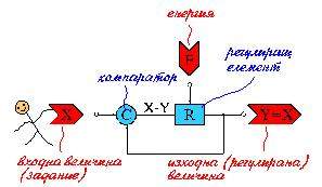
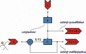
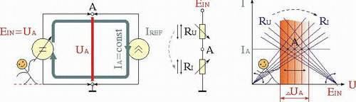
7.1. Elementary system with negative feedback (active follower). Negative feedback (NFB) principle: deriving the idea from many everyday situations (analogies); generalizing in a block diagram. Behaviour presented through the operations of comparison and regulation. Constituent components: comparator and regulating element.
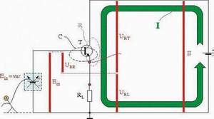
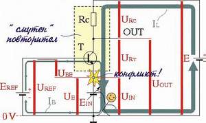
7.1.1. Emitter (source) follower unloaded. Building the circuit by using the block diagram. Visualizing the operation by a potential diagram. Discussion: What does act as a comparator in the circuit of the emitter follower?
7.2. NFB system disturbed. Discussion: How do the active followers react to the harmful disturbances in the day's routine? What are their advantages in comparison with the passive followers? What do they have to have in order to compensate big disturbances?
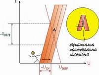
7.2.1. Emitter (source) follower loaded. Applications: transistor voltage regulator (stabilizer) - building 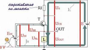 from RD stabilizer and emitter follower. Discussion:
 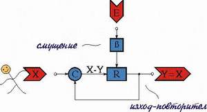 How does the transistor transmute from a current source into a voltage source? Exploring the circuit at a varying load and voltage supply (in comparison with common-emitter stage.
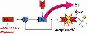
7.3. NFB amplifying system. Discussion: Are there useful disturbances? May we use the reaction of an active follower to the disturbances as an input? Converting the active follower into an amplifier by deliberately disturbing.
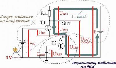
7.3.1. Common-emitter amplifier. Converting the emitter follower into an amplifier by introducing a "disturbing" resistor RC. Discussion: Can the circuit act as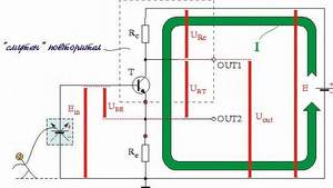
 a follower and even as an attenuater?
7.3.2. NFB transistor current source. Converting the emitter follower into a current source/sink. Exploring at a varying load and supply voltage.
7.3.3. Common-base amplifier. How do the active followers react when we try to change "brutally" their output value? "Inventing" the circuit by disturbing an emitter follower in the output. Discussion: What is the function of the collector resistor RC? To what extent may we change the circuit output voltage? Why is the circuit non-inverting?
 |
 |
 |
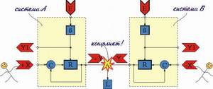
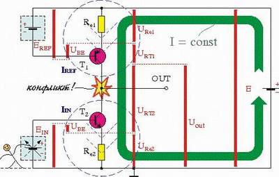
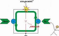
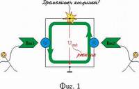
7.4. Differential amplifying system. Discussion: How do the active followers interact (aid or oppose) in life? Examples (popular games): arm fighting. How can we apply the phenomenon of conflict in the electronic circuits? How can we cause a conflict of potentials?
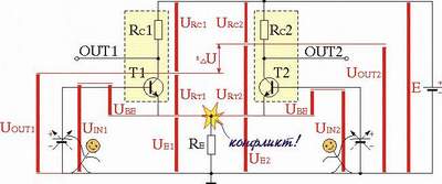
7.4.1. Transistor differential amplifier.
7.4.1.1. Building the circuit.
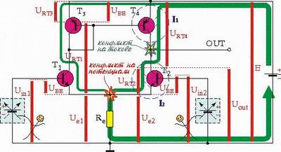
SCENARIO 1: Assembling the circuit from a voltage comparator with current output (a transistor controlled by the base and by the emitter + current-to-voltage converter + boosting emitter follower.
SCENARIO 2: Assembling the circuit from emitter followers with a common output. Discussion: Why is the emitter resistor RE needed? Can we make the circuit without RE (hint - try to use heterogeneous transistors)?
 |
 |
 |
7.4.1.2. Exploring the circuit (visualizing with potential bars) at:
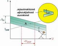
* single-ended input signals. Presenting the circuit as consecutively connected emitter follower and common-base stage. Linking with digital electronics. What is emitter-coupled circuit?
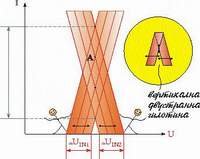
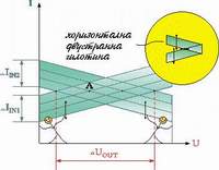
* differential input signals. Presenting the circuit as contrary connected emitter followers. Discussion: Might we name the common emitter point virtual ground? Is the resistance of the common emitter resistor RE crucial in this case? Is the resistor RE necessary?
* common-mode input signals. Presenting the circuit as cooperatively connected emitter followers. Discussion: What is the role of the common emitter resistor RE in this case? May we take a single-ended output from the one of collectors?
7.4.1.3. Improving the circuit by replacing the resistor RE with a current source. Revealing the phenomenon of aiding in electronic circuits. Discussion: How does an emitter follower (voltage source) behave when it is loaded with a current source? Is the emitter element really a current source?
 |
 |
7.4.1.4. Improving the circuit by replacing the collector resistor RC with a current source. Revealing the phenomenon of current conflict in electronic circuits. Building an amplifying stage with dynamic load. Discussion: How does a transistor current source behave when it is loaded with another current source?
Building the amplifier with a dynamic load. Is this arrangement correct? |
 |
|
 |
 |
|
Building the amplifier with a dynamic load. |
 |
|
 |
 |
|
7.4.2. An operational amplifier. Building the circuit by improving the differential amplifier with additional building blocks. Functional notion of an operational amplifier as voltage controlled voltage source. Discussion: What is the role of the bipolar supply in the op-amp circuits? Applications: The op-amp as a comparator.
Last updated October 26, 2004
home - bg - intro - contents - library - resources - feedback - digital