home - bg - intro - contents - library - resources - feedback - digital
1 2 3 4 5 6 7 8 9 10 11
ANALOG ELECTRONICS - 2004
What we do at the Class Exercise 2 (March 8 - 13, 2004)
Elementary Passive Converters with Voltage Output
Second Viewpoint: Current Causes Voltage ...
At Class 2 we will derive a further 10 elementary building blocks which we will put in the library; thus it will contain a total of 20 basic circuits so far:
| indivisible building blocks |
sources/loads |
current source |
voltage load |
| converters |
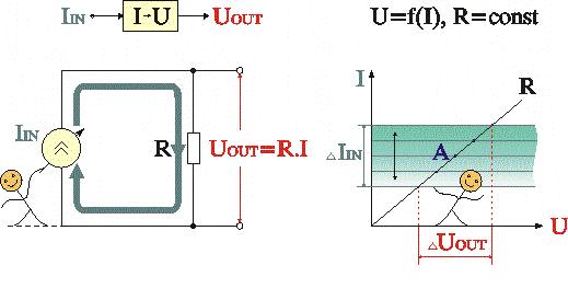
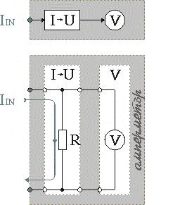
current-to-voltage converter |
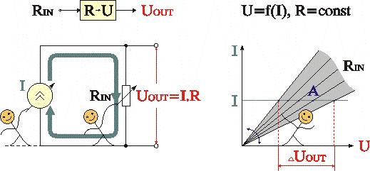
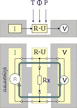
resistance-to-voltage converter |
| compund building blocks |
voltage sources |
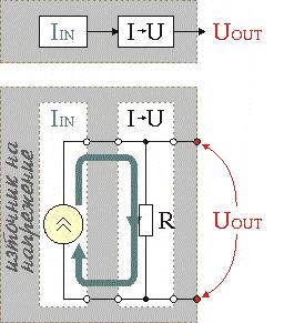
current-controlled voltage source |
resistance-controlled voltage source |
| measuring devices |
ammeter |
linear ohmmeter |
| multi-input devices |
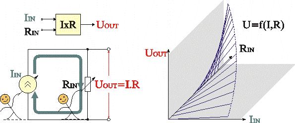
current-by-resistance multiplier |
parallel current summer |
PHILOSOPHY. Assuming that pressure causes flow, respectively voltage causes current, we have managed to derive a few extremely useful passive analog devices (class 1). Now let's assume just the rather way round - flow causes pressure respectively current causes voltage. Using a lot of analogies, we may introduce again an intuitive notion of this phenomenon.
Funny "experiment". Maybe, the funniest of them is an old-fashioned vacuum-cleaner which sucks and blows (at the same time) an air through a closed rubber loop. What do you think, what is the pressure trough the loop? Thank you for the answer; now let's pinch the hose in the middle. Again, what is the pressure trough the pinched hose?
Suggestions: Can you give more analogies (as possible funnier) where something moves; then it encounters an obstacle and, as a result, a pressure appears? An example: a student moves calmly through (climb on) the educational "ladder"; but he encounters a "bad" teacher and, in order to take an exam, the student ... wield a pressure on the teacher :). Or v.v., a teacher who ...... :).
All these experiments suggest finally that ... we have to supply the elementary Ohm's circuit by a constant current source instead a voltage one.
What do you thin;, could Ohm carry out this experiment? Well, let's go on ...
VARYING current or/and resistance as input variables and taking voltage as an output one we, figuratively spoken, "invent" the next three elementary indivisible circuit building blocks: passive current-to-voltage converter, resistance-to-voltage converter and current-by-resistance multiplier. As you already know, in order to visualize the invisible electrical attributes, we present voltages by potential bars with heights corresponding to their values, potential diagrams and superimposed IV curves; also we present current by a corresponding thickness of a current loop.
Questions: What is an ideal I-to-V converter? Does it exist? What does it really do? What is the relation between the input and output value of the ideal I-to-V converter (R-to-V converter)? Is an I-to-V converter a reversible device? What happens if we swap its input and output? Is an R-to-V converter a reversible device? Is the R-to-I converter a linear device? What is a quiescent point of a V-to-I (an R-to-I) converter? How do we visualize it?
COMBINING the elementary blocks into more complicated compound blocks we build useful devices: current-controlled voltage source (after Norton); compound ammeter made from a voltmeter; resistance-controlled voltage source; compound ohmmeter made from a voltmeter; future devices (briefly) - multiplying R-2R ladder DAC with an input (reference) current and an output voltage.
We can even write building "formula" for each compound building block:
current-controlled voltage source = current source + current-to-voltage converter,
compound ammeter = current-to-voltage converter + voltmeter,
resistance-controlled voltage source = current source + resistance-to-voltage converter,
compound ohmmeter = current source + voltmeter etc. Give more examples ...
Questions: Are all the passive circuits ideal devices? What is an ideal voltage load - give examples from electricity, measuring, semiconductors ...? Can it really exist? Is it possible to measure something not consuming energy? Is the electrostatic voltmeter an ideal device?
A problem: Can you measure a big current (10 A) by using only 0.1mA meter movement (with 1 k internal resistance) without any shunt resistor?!? Hint: may we connect an ammeter as a ... voltmeter? Ask Stoyan and Radi for more hints!
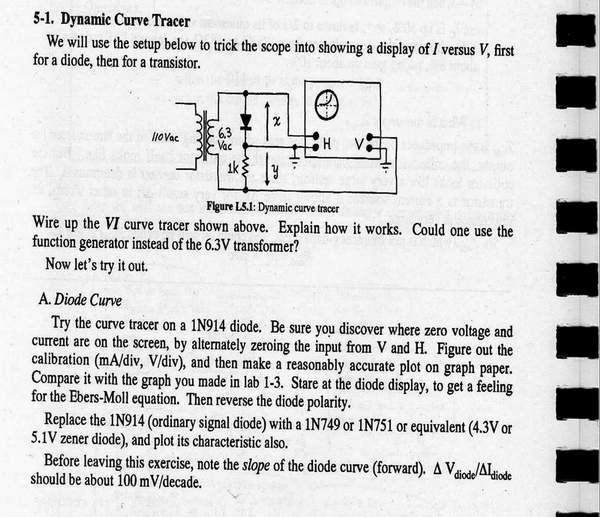
A small project: Dynamic curve tracer. Design a setup consisting of a transformer, resistor and a diode (ordinary, zener, LED) in order to visualize the diode's IV curve (VMAX = 5.6V, IMAX = 10 ma) on a oscilloscope. Can you connect the components in a way that will allow tricking the scope into showing a display of I versus V without any errors? What is the function of the resistor in this arrangement? Can we say that it functions as a perfect current-to-voltage converter? What is the function of the diode? Can we say that it functions as a voltage-to-current converter?
IMPERFECTIONS. Do you remember that all the passive circuits with current output were ideal devices!? Well, more precisely speaking, they worked at ideal load conditions (with "shorted" output). Only, do you remember how they changed for the worse once we try to consume their output current with a real load? The circuits discovered here are exactly such loads.
Questions: What kind of input source does an I-to-V converter "like"? What is the input resistance of the I-to-V converter? What happens if we drive the converter with a real current source?
What kind of load does voltage-output converters "like"? What is the output resistance of these converters? What happens if we load the converter's current output with a real load?
IMPOVING. We begin looking for a remedy - how do we reduce the errors caused by the real current source and the real voltage load? Thus, we will draw a conclusion to reduce the error by reducing the resistance. Of course, we would improve the input current source if it is an accessible. But if it is not accessible?
IDEALIZING. Obviously, when a current-output circuit (acting as a generator) drives voltage-output circuit (acting as a load) a contradiction appears: from one hand, the load has to be low resistive in order not to disturb the input source; from the other hand, it has to have high resistance in order to have high sensitivity. In other words, the load has to exist and it has not to exist at the same time?!? How is it possible? Well, let's begin looking for an ideal solution right now, in the kingdom of the voltage-output passive circuits. Quite later, this remedy will enable us to convert the imperfect passive circuits with voltage output into almost ideal ones. What is more ...
GENERALIZING. At the next classes (3, 4 and 5) dedicated to the rest passive circuits we will continue looking for a universal principle (a philosopher's stone :) for converting every imperfect passive circuit into an almost ideal one. What do you think; is there such a principle? And where do we look for it?
Questions: What is the difference between the passive and the active versions of the voltage output converters?
Is there any relationship between them?
ENLARGING. Once Kirchhoff's voltage law has helped us to derive so useful passive building blocks why don't we try to do the same by using Kirchhoff's current law?
If we connect a few current sources in parallel to the load we will get another useful summing circuit - parallel current summer. Quite later on, using this building block, we will assemble famous electronic circuits with parallel negative feedback.
Finally, another great idea dawns on us - to connect (incorrectly?) two current sources to each other and then to begin varying their currents in opposite or in the same directions. Thus we get powerful ideas for future building "absurd" electronic circuits with dynamic loads.
Class 2 as a Table
Why don't we present Class 2 again in a form of table? Let's try! Here is a basic table. Add additional rows and columns to enrich it!
| Block |
Potential bars, current loops |
Potential diagram |
Working point
(IV intersection) |
Transfer characteristic
|
Function |
Imperfections |
| 1. I > V |
|
Animation |
|
|
IOUT = f(VIN) |
Animation |
| 2. R > V |
? |
? |
|
|
IOUT = f(RIN) |
IOUT = f(RIN) |
| 3. IxR >V |
|
? |
|
|
IOUT = f(VIN,RIN) |
IOUT = f(VIN,RIN) |
| ... |
|
... |
|
...
|
... |
... |
Related web sites
Dynamic curve tracer. Design a setup consisting of a transformer, resistor and a diode (ordinary, zener, LED) in order to visualize the diode's IV curve (VMAX = 5.6V, IMAX = 10 ma) on a oscilloscope. Can you connect the components in a way that will allow to trick the scope into showing a display of I versus V without any errors? What is the function of the resistor in this arrangement? Can we say that it functions as a perfect current-to-voltage converter? What is the function of the diode? Can we say that it functions as a voltage-to-current converter?
Well, let's see how Tom Hayes has solved this problem in the Student Manual for the Art of Electronics (page 118).
|
|
Now, let's also see what Tony Kuphaldt (Bellingham Technical College, Washington) says in his Lessons In Electric Circuits. In Chapter 2 he reasons how voltage, current, and resistance relate; then he introduces a fluid analogy for Ohm's law.
Browse also Topical worksheets from his great project of Socratic electronics; you may find there interesting questions.
Let's see also the more practical basic electronics course of Basic Car Audio Electronics maintained by Perry Babin. This course shows many applications in the cars. Perry has dedicated a separate page to various resistor applications (e.g. including current limiting) which we may apply in the class 2.
In his Intuitive electronics Glen Williamson shows how a resistor may act as a passive current-to-voltage converter.
An interesting DC-circuit water analogy is presented in hyperphysics by Rod Nave.
Send your questions, views and suggestions about this topic to cyril@circuit-fantasia.com
Last updated
January 8, 2007
1 2 3 4 5 6 7 8 9 10 11
home - bg - intro - contents - library - resources - feedback - digital