 Inventing Circuits on the Whiteboard...

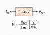
Passive Current-to-Voltage Converter
As regards the circuit inputs, we prefer voltage to current as an input quantity. Only, some devices have a current input (an ammeter, a bipolar transistor, a transimpedance amplifier, a Norton amplifier, etc. In these cases, we connect a voltage-to-current converter before the device; as a result, it acquires a voltage input.
Similarly, we prefer voltage to current as an output quantity. Only, there many devices having a current output (actually all the active electronic components - a current source, a bipolar transistor, a tube, a FET transistor, etc.) In these cases, we need to connect the reverse current-to-voltage converter after the device, in order to get a voltage output. Since the current-output devices are more widespread than current-input ones, this circuit is more popular than the opposite voltage-to-current converter. Then, let's build it!
As usual, there are two versions of this circuit - passive ("bad") and active ("good"); here, we begin with the "bad" passive version. Then, in another story dedicated to the "good" active version, we will show that there is a close interrelation between the two circuits: the active version is come from the passive one (the active version comprises the passive one, it is just an improved passive version). In this way, we will show the evolution of the famous circuit moving, step-by-step, from simple to complex.
Internal links:
1. Non-electrical domain: Flow causes pressure
2. Electrical domain: Current causes voltage
3. Exploring the circuit operation in an attractive manner
4. I-to-V converter acting as an output device
5. I-to-V converter acting as an intput device
6. What are the input/output resistances?
7. What are the imperfections of the passive version?
8. Can we improve the imperfect passive circuit?
Color key
Links: this page, other my pages, external, multimedia, handmade.
Text: analogies, conclusions.
The basic idea behind the circuit
top < prev step - 1 - 2 - 3 - 4 - 5 - 6 - 7 - 8 - next step > end
Non-electrical domain : Flow causes pressure
Trying to find an answer to the question, "What causes what?" in the previous story, we assumed that pressure causes flow. Only, there are many situations in our routine where flow causes a pressure. In these case, something moving encounters an obstacle; as a result, a pressure appears. Here are some examples.
Mechanical: If we try to stop a moving car with our body:), it exerts pressure to us.
Pneumatic. Imagine a constant flow pump moving air through a closed loop of pipes (we may carry out such a funny experiment by using an old-fashioned air cleaner, which sucks and blows air through a closed loop made from a corrugated hose). Pinch the hose in the middle and you will see that a pressure appears across the bottleneck (the upper part lengthens while the lower shortens).
Social: Stand in someone's way and you will experience "pressure", etc.
Conclusion. If we pass a flow through an impediment, a pressure will appear. In this arrangement, the flow-like, pressure-like and impediment-like attributes are interrelated as before. Usually, the output pressure-like variable is proportional to the input flow-like one:
In order to induce a pressure, we have to put an impediment in flow's way.
The impediment can convert the flow-like variable into a pressure-like one.
Building a simple passive circuit
top < prev step - 1 - 2 - 3 - 4 - 5 - 6 - 7 - 8 - next step > end
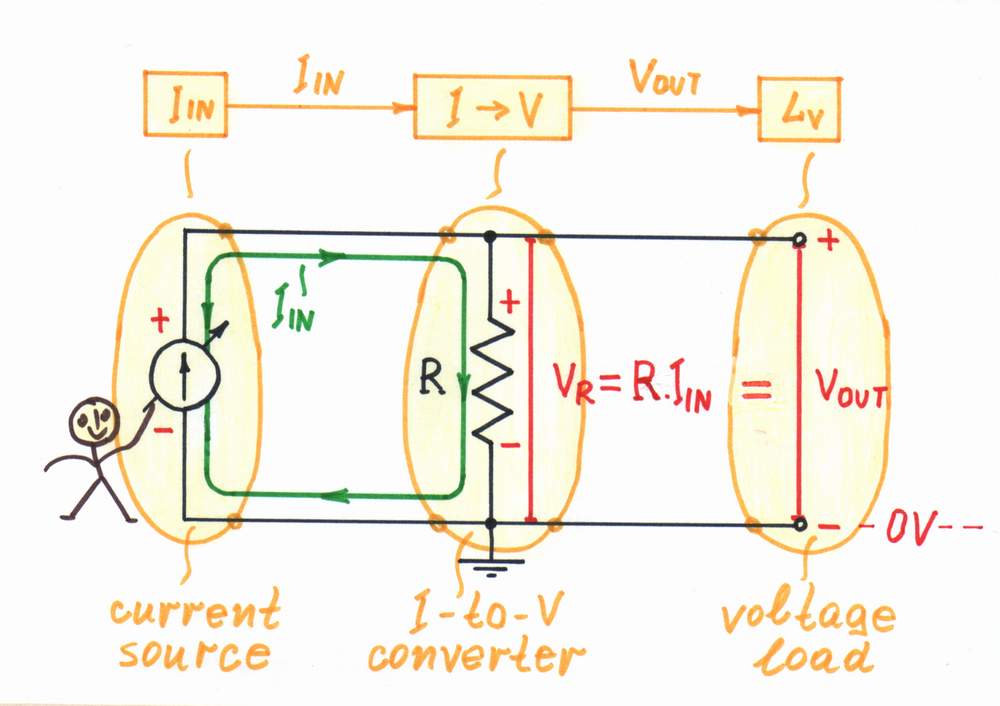
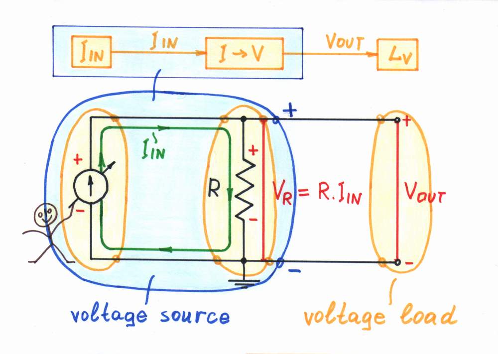
In electricity, we may observe an analogous current-causes-voltage phenomenon: if a current IIN flows through a resistor R, the latter impedes (resists) the current; as a result, a proportional voltage drop VR = R.IIN appears across the resistor. In this current-supplied circuit, the voltage drop VR acts as an output voltage VOUT. Only, note that the voltage drop VR is created not by the resistor; it is created by the excitation voltage source inside the input current source.
We may say that this is a current-causes-voltage formulation of Ohm's law:
V = R.I
In this current-supplied circuit, the resistor R determines the voltage across it. We usually say that the resistor converts the current IIN into a proportional voltage VOUT or it serves as a simple current-to-voltage converter - a linear circuit with transfer ratio k = VOUT/IIN [V/mA].
A bare resistor can convert current into voltage.
Electrical domain : Current causes voltage
Exploring the circuit operation in a more attractive manner...
top < prev step - 1 - 2 - 3 - 4 - 5 - 6 - 7 - 8 - next step > end
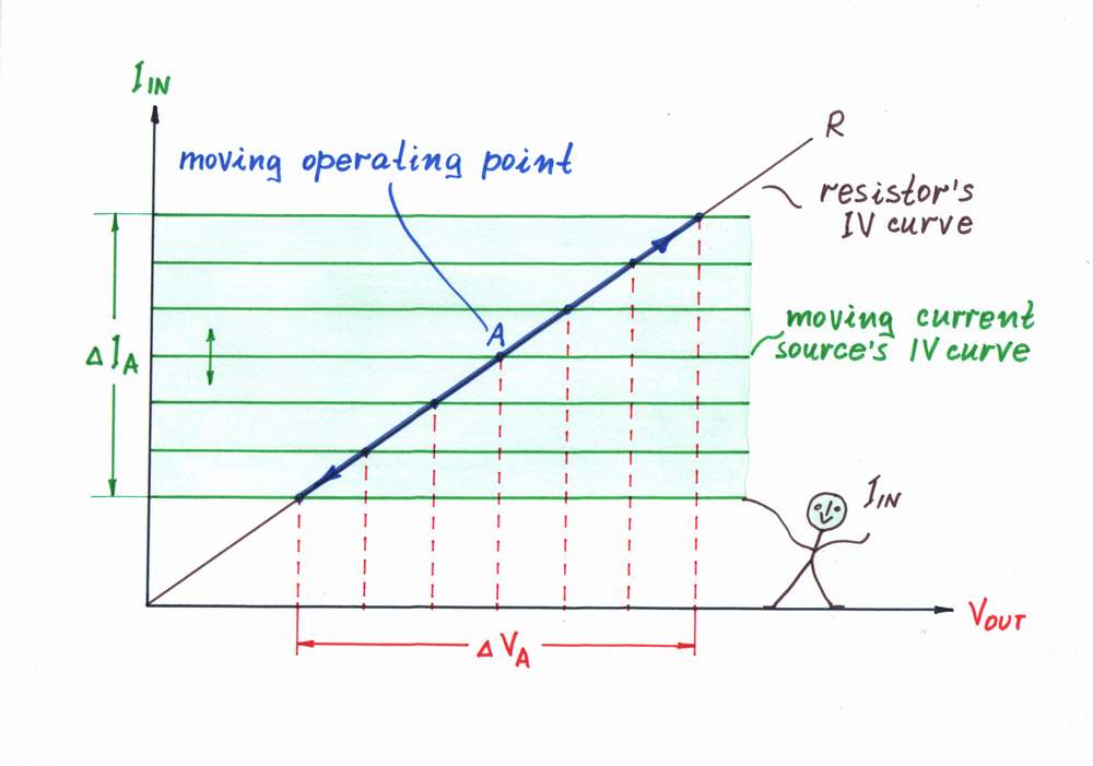
Circuit operation. We may present the circuit operation and Ohm's law in a more attractive manner than V = R.I, if we visualize the invisible electrical quantities by means of voltage bars and current loops (see the circuit diagram above). If you remember, in this "geometrical" presentation, the thickness of the current loop is proportional to the magnitude of the current and the height of the voltage bars is proportional to the corresponding voltages or drop (see also an interactive animation).
Then, we may present the circuit operation (and Ohm's law) graphoanalytically (see the picture on the right). As the voltage across and the current through the two 2-terminal components (the voltage source and the resistor) are the same, we may superimpose their IV curves on a common coordinate system. The intersection of the two lines is the operating point A; it represents the current magnitudes of the current IA and the voltage VA.
When we vary the current of the input current source, its IV curve moves vertically (see also an interactive animation). As a result, the working point A slides over the IV curve of the resistor R; its slope represents the converter's ratio.
...by superimposed IV curves
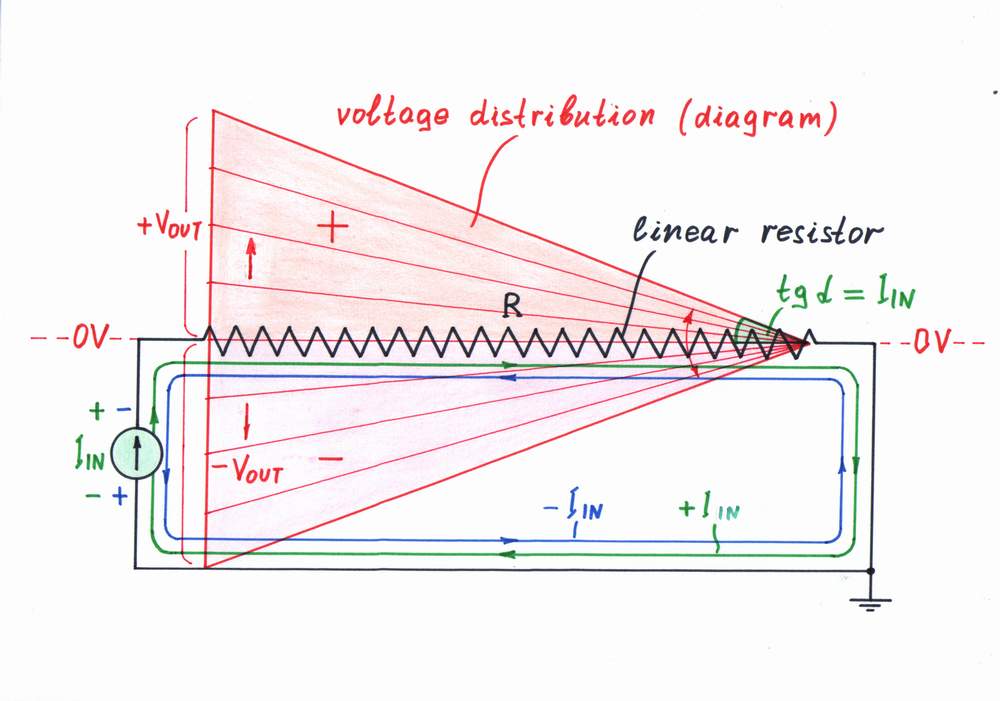
As before, we may use another attractive graphical interpretation of Ohm's law - the voltage diagram (the voltage distribution along the resistive film inside a linear resistor). Here, when the input current varies, the local voltages along the resistive film vary decreasing gradually from left to right (see also another interactive animation). In this arrangement, the angle α represents the input current IIN.
...by a voltage diagram
Applications: I-to-V converter acting as an output device
top < prev step - 1 - 2 - 3 - 4 - 5 - 6 - 7 - 8 - next step > end
Current-controlled voltage source. Although there are enough constant voltage sources in nature (primary and secondary batteries), if there is a current source but we need a voltage source, we may build it. For this purpose, we connect a current-to-voltage converter after the current source:
Voltage source = current source + current-to-voltage converter
That means just to connect a humble resistor R in parallel to the input current source IIN (the Norton's idea in electricity).
If the load is ideal (that is, it has an infinite resistance), this compound voltage source will generate a constant voltage VOUT = R.I. This voltage will affect the current, if the input current source is imperfect (see imperfections).
Current-controlled voltage source
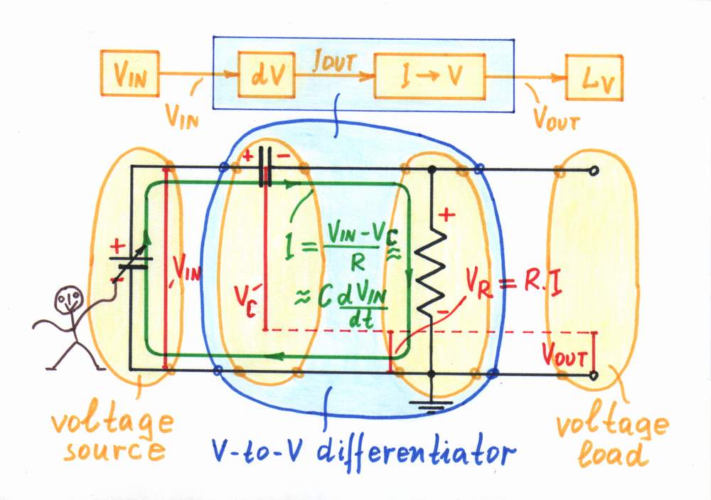
Compound passive converters: Similarly, in the popular passive circuits of capacitive differentiator, inductive integrator, antilogarithmic converter, etc., the resistor acts as a current-to-voltage converter:
V-to-V CR differentiator = V-to-I C differentiator + I-to-V converter
V-to-V LR integrator = V-to-I L integrator + I-to-V converter
V-to-V DR antilog converter = V-to-I D antilog converter + I-to-V
For example, a classic capacitive-resistive differentiator on the figure is built by using the simpler voltage-to-current capacitive differentiator (a bare capacitor) and a current-to-voltage converter.
In these circuits, the resistor R acting as a current-to-voltage converter introduces some voltage drop VR, which affects the excitation voltage VIN. As a result, the current decreases and an error appears (see imperfections).
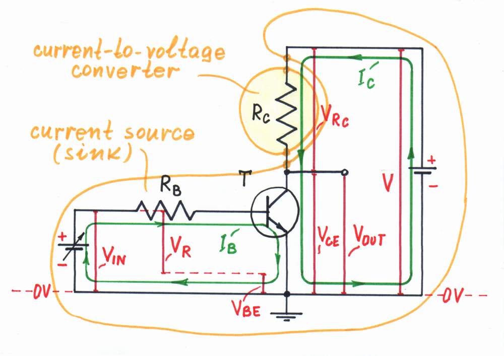
Transistor collector resistor. Transistor is a current-generating device. Therefore, in order to obtain a voltage as an output, a collector resistor is connected in the output circuit of the transistor stage. Examples of this technique are the common-emitter, common-base and differential amplifier, a transistor switch, etc.
Voltage-output transistor = Current-output transistor + I-to-V converter
The transistor's collector resistor acts as a current-to-voltage converter.
Since the voltage drop VRc is floating, usually the complementary (to the power supply) voltage drop VCE is used as an output. As a result, these transistor circuits are inverting (when the input voltage rises, the output voltage drops and v.v.)
A similar technique is used, in order to obtain a voltage in the transistor emitter of the negative feedback current source. Examples of this technique are all the transistor circuits using series negative feedback.
The transistor's emitter resistor acts as a current-to-voltage converter.
V-to-I converter acting as an input device
top < prev step - 1 - 2 - 3 - 4 - 5 - 6 - 7 - 8 - next step > end
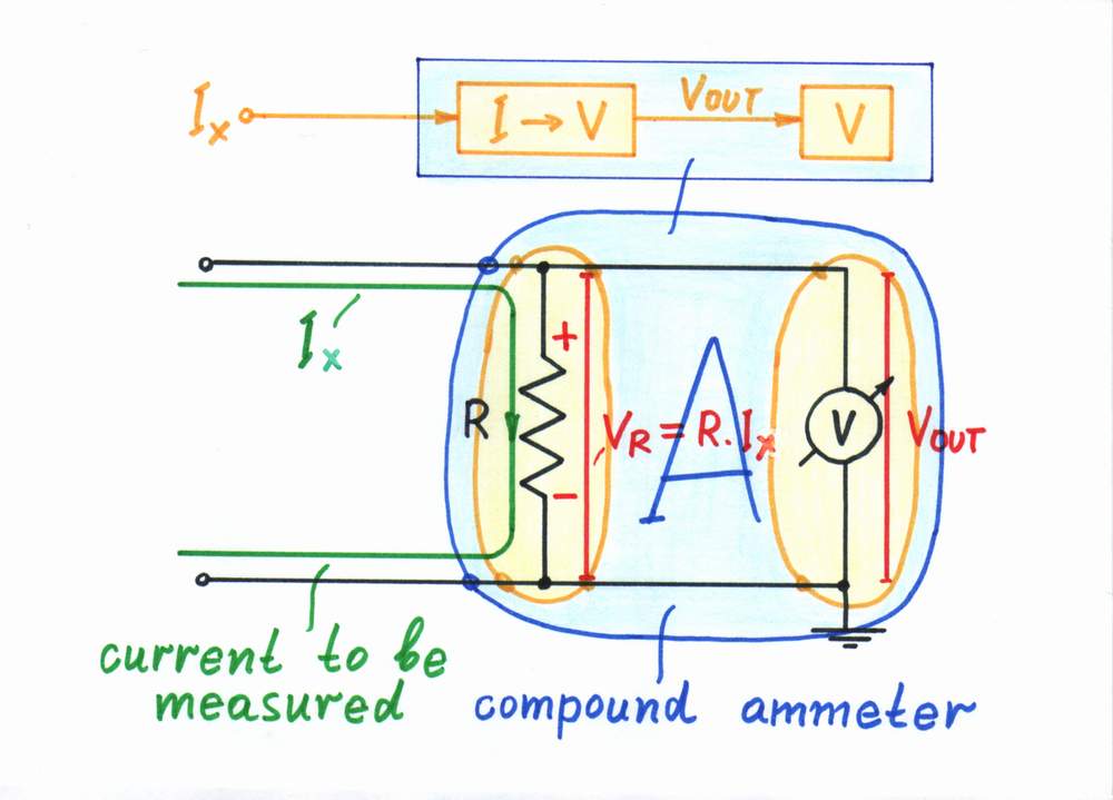
Compound ammeter. Today's measuring instruments (DVM's, analog-to-digital converters, etc.) are mainly voltmeters. If there is a need to measure a current, we connect a simple current-to-voltage converter (a shunt resistor) before the voltmeter. This ammeter is a composed device consisting of two components:
Compound ammeter = Current-to-voltage converter + voltmeter
The shunt resistor of a composed ammeter acts as a current-to-voltage converter.
Although the active version is the perfect current measurement solution, the popular multimeters use exactly the passive version, in order to measure big currents (see power considerations).
I-to-V converter as a part of active V-to-I converters
Negative feedback systems have the unique property to reverse the causality in the electronic converters connected in the feedback loop. Examples: an op-amp non-inverting amplifier is actually a reversed voltage divider, an op-amp integrator is a reversed differentiator and v.v., an op-amp logarithmic converter is a reversed antilogarithmic converter and v.v., etc.
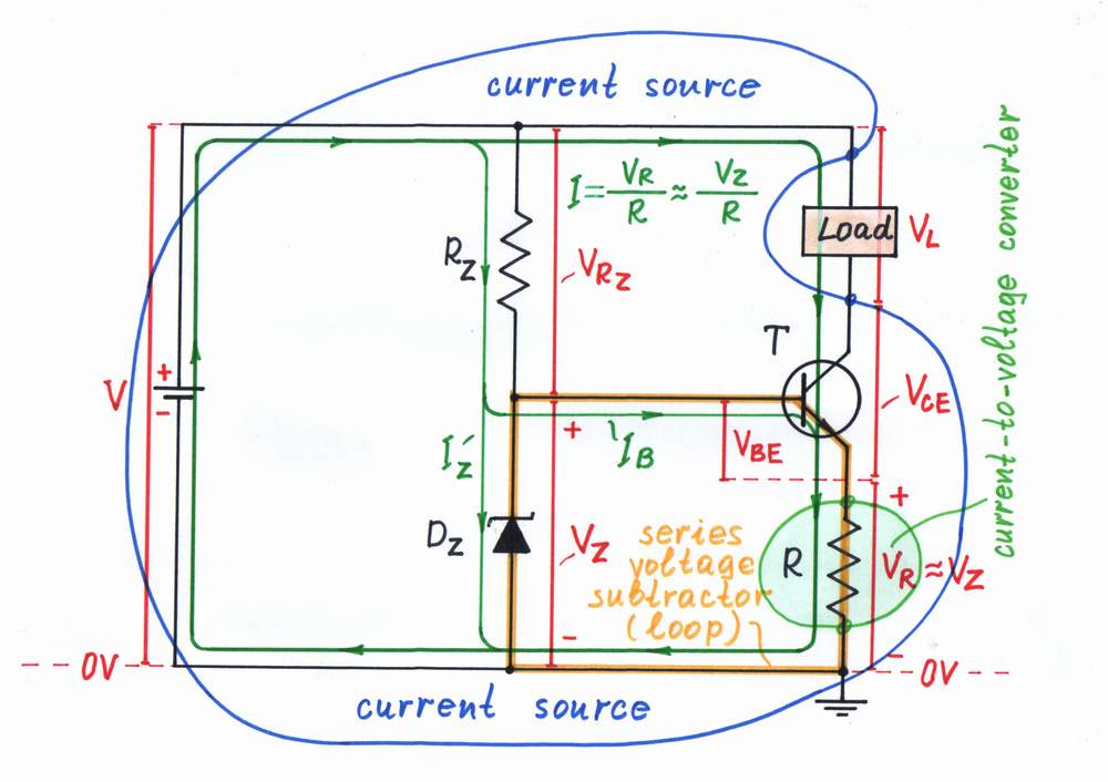
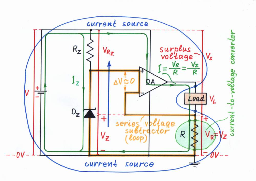
Similarly, an op-amp voltage-to-current converter (a voltage-controlled constant current source) built by using a negative feedback is actually a reversed current-to-voltage converter. This powerful idea is implemented as a transistor version of a current source (the figure on the left) and as an op-amp version of a current source. In these circuits, a current-to-voltage converter (the bare resistor R) is connected in the negative feedback loop. The voltage drop VR proportional to the load current I is compared with the input voltage VZ. For this purpose, the two voltages are connected in series and their difference dV = VZ - VR is applied to the input part of the regulating element (the base-emitter junction of the transistor T or the differential input of the op-amp OA). As a result, the regulating element establishes the current I = VR/R ≈ VZ/R by changing its output resistance so that to zero the voltage difference dV. In this way, the output current is proportional to the input voltage; the whole circuit acts as a voltage-to-current converter.
What are the input/output resistances?
top < prev step - 1 - 2 - 3 - 4 - 5 - 6 - 7 - 8 - next step > end
Do you remember that when we were considering the opposite voltage-to-current converter, we were investigating the input and output resistances? Let's do the same for the present current-to-voltage converter. Again, let us for concreteness assume a resistive load RL.
What is the input resistance?
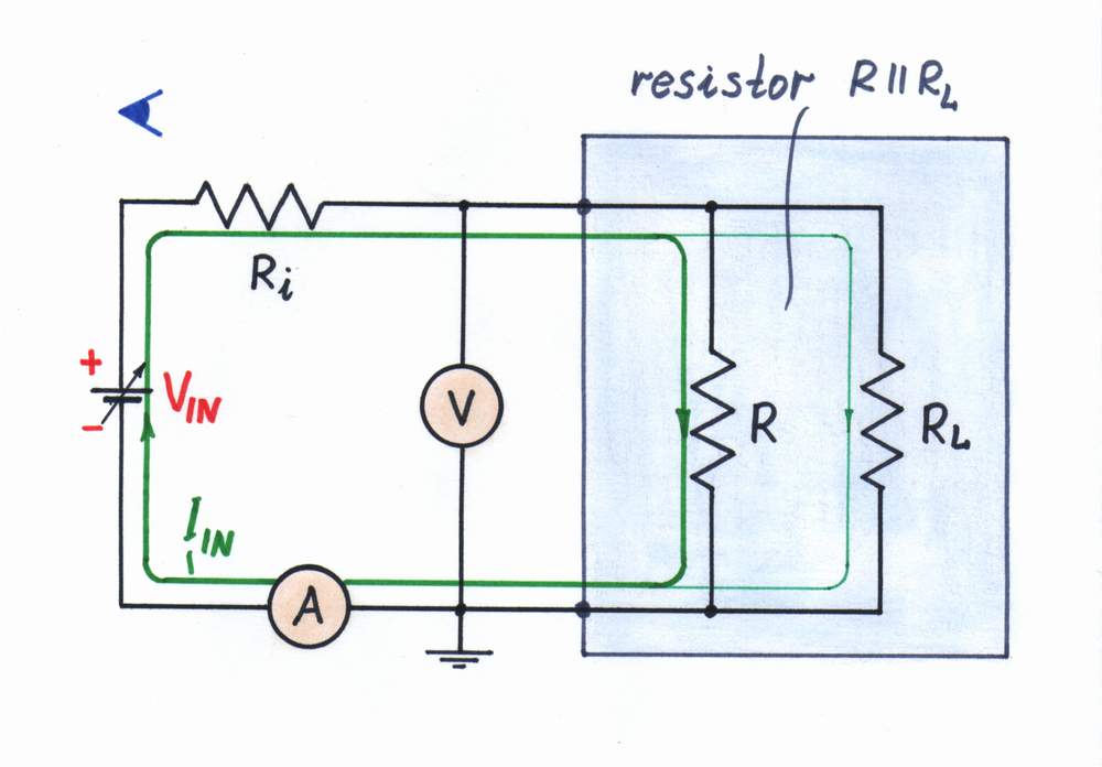
First, connect an ammeter in series with and a voltmeter in parallel to the converter's input; then vary the input current to investigate the input resistance. Looking from the side of the input source we see two resistors connected in parallel - R and RL; so, the input resistance is RIN = R||RL. As you can see, it depends on the load resistance RL. Only, we choose R << RL; so, RIN ≈ R.
What is the output resistance?
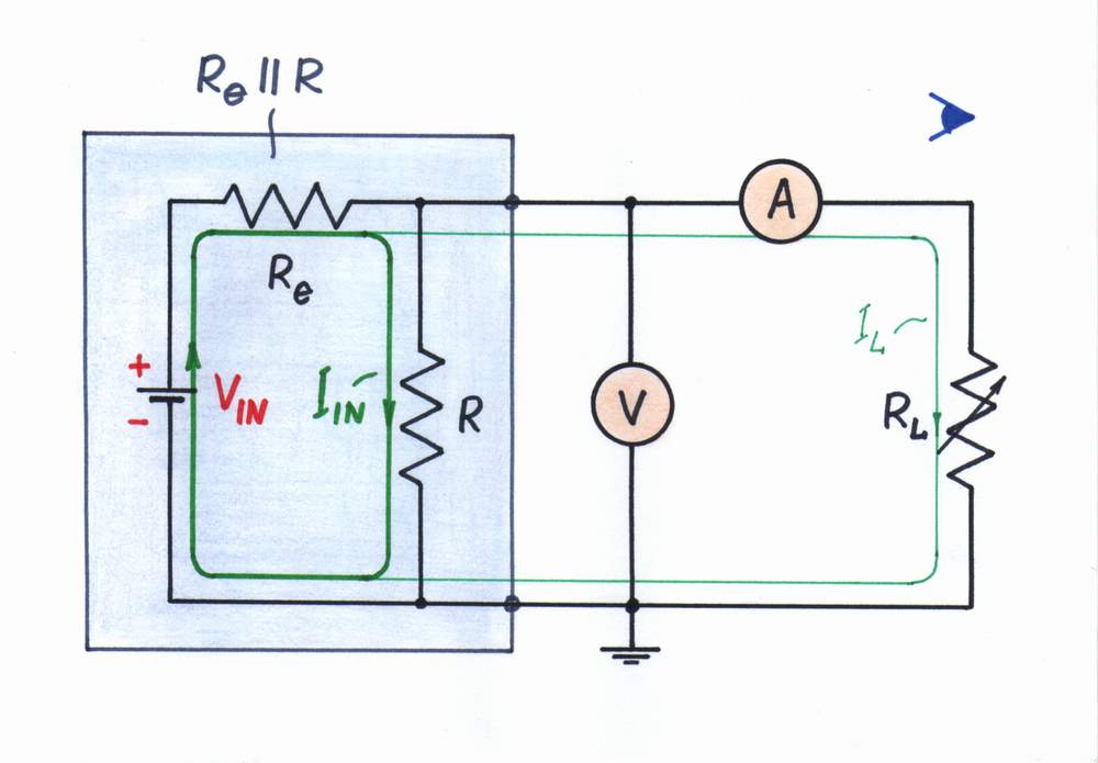
Now, connect a voltmeter in parallel to and an ammeter in series with the converter's output; then, vary the load resistance (voltage) and observe the current to investigate the output resistance. Looking from the side of the load, we see two resistors connected in parallel - Re (the equivalent resistance of the input circuit) and R; so, the output resistance is ROUT = Re||R. If the input current is created by an ideal current source, the output resistance is only ROUT ≈ R.
Imperfections
top < prev step - 1 - 2 - 3 - 4 - 5 - 6 - 7 - 8 - next step > end
A problem. Only, a strange contradiction appears here. From one side, the voltage drop VR across the resistor R is useful for us (this is the output voltage needed!). From the other side, this voltage drop is harmful as it enervates the excitation voltage VIN (here we suppose that the input current is created by a voltage source VIN through the resistor Ri). Now the voltage difference VIN - VR determines the current instead the voltage VIN. It turns out that measuring the current we disturb it! As a result, the current IIN decreases:( What do we do to solve this contradiction?
You can explore the circuit imperfections in a more attractive way, if you click Exploring button in the interactive flash movie or if you go to Stage 2 in the interactive flash builder.

Improvement
top < prev step - 1 - 2 - 3 - 4 - 5 - 6 - 7 - 8 - next step > end
Classic remedy. We can decrease the error caused by the resistor R by decreasing its resistance. Only, the output voltage will decrease as well and probably we have to amplify it. Doing that, we will also amplify the noise... How to solve the problem then?
Looking for a perfect remedy. Obviously, we have to solve the contradiction so that the resistance R to exist and, at the same time, not to exist!?! How do we do this magic? A tip: remember what we do in life when something bad appears.
If you do not manage to find a remedy, visit the pages below; they might suggest how to figure out the problem.
How do we create a virtual ground?
Inverting op-amp RC integrator
Inverting op-amp current source
Wikibooks: Circuit idea - Op-amp inverting voltage-to-current converter
Links to related web resources
Elementary passive converters with voltage output is a teacher's story about the simplest electric converters (from the exercices with my students, 2004).
Reinventing the transimpedance amplifier reveals the philosophy of the famous circuit (see the passive version in the beginning).
Op-amp circuit builder shows how to transform any passive converter into an active one (choose the resistor R2 from the library on the right side).
Wikibooks > Circuit Idea > Passive current-to-voltage converter reveals the idea behind the passive version.
Wikipedia: Current-to-voltage converter is dedicated to the passive and active versions of the current-to-voltage converter.
Resistors and Transistors show how a base resistor can act as a simple voltage-to-current converter (well illustrated and animated).
Ammeter design presents a classic but useful viewpoint at the compound ammeter (see the last part).
Low Current Measurements AN1 of Keithley (the introductory part) scrutinizes the imperfections of the passive current-to-voltage converter.
circuit idea - circuit-fantasia > circuit stories > inventing circuits > passive current-to-voltage converter
Last updated July 14, 2007