home - bg - intro - contents - library - resources - feedback - digital
1 2 3 4 5 6 7 8 9 10 11
Class Exercise 8 (May 10 - 15, 2004)
8. Op-amp Amplifiers with Negative Feedback
So far, we have build a total of 59 circuit building blocks. Now, using the famous op-amp and the powerful negative feedback principle, we will build almost ideal circuits. Thus, we will enrich the library with a further 9 building blocks; so, it will grow to 68 basic circuits:
| Op-amp followers |
| follower (non-inverting amplifier with K = 1) |
invertor (inverting amplifier with K = -1) |
| Op-amp disturbed followers |
| proportional disturbed followers |
additive disturbed followers |
| with series NFB |
with parallel NFB |
with series NFB |
with parallel NFB |
| followers |
invertors |
followers |
invertors |
| Op-amp amplifiers with negative feedback |
| with series NFB |
with parallel NFB |
with mixed NFB |
| non-inverting amplifier |
inverting amplifier |
differential amplifier |
8.1. Op-amp followers. Discussion: Why do we convert a very good amplifier ( with K > 100000) into ...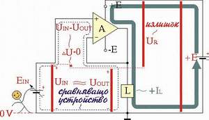 a follower (K=1)?
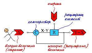
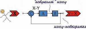
8.1.1. Op-amp follower with series NFB. Building the circuit by using the block diagram. Discussion: What does act as a subtractor (comparator) in this circuit? Why is the circuit non-inverting? What have to be the op-amp in this circuit (regarding the inputs)? To what limits may we varying the input voltage?
8.1.2. Op-amp follower with parallel NFB. Building the circuit by using the block diagram: assembling from a parallel voltage summer. Visualizing the operation by a potential diagram. Discussion: What does act as a subtractor (comparator) in this circuit? Why is the circuit inverting? What have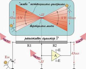
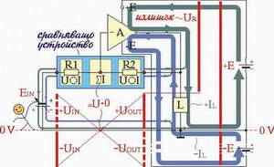 to be the op-amp in this circuit (regarding the inputs)? To what limits may we varying the input voltage? May we connect the virtual ground to the real ground since it is a kind of ground?
8.2. Op-amp follower disturbed. Discussion: Where have to be connected the "disturbing" element in order to be compensated its harmful influence? When a virtual ground is not a ground?
8.2.1. Multiplicative (proportional) disturbances caused by the op-amp output resistance ROUT, lead resistance and load resistance. Applications: eliminating the ROUT; "hiding" a current limiting resistance; voltage carrying without losses over a long line. Visualizing the applications by potential bars.
8.2.2. Additive disturbances caused by "voltage-shifting" diode and transistor elements. Applications: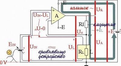 eliminating the forward voltage drop VF across a diode in the circuit of series diode limiter (ideal diode); eliminating the base-emitter voltage drop VBE0 in the circuit of emitter follower (booster) connected in the op-amp feedback loop. Visualizing the applications by potential bars.
 8.3. Op-amp NFB amplifier. A principle attenuation causes ... amplification. Discussion: Where have to connect the deliberately disturbing element in order to obtain an amplification?
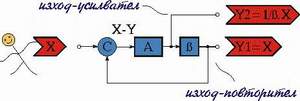
8.3.1. Non-inverting amplifier. Converting the op-amp follower into an amplifier by introducing a "disturbing" voltage divider. Visualizing the operation by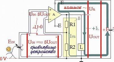 potential bars. Building a circuit
 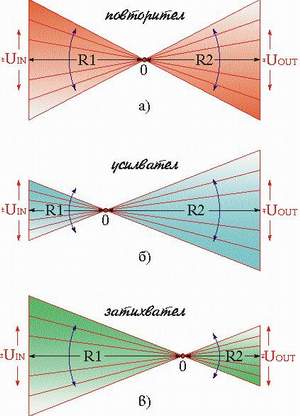 with T-bridge in the feedback loop by using a "double disturbing".
8.3.2. Inverting amplifier. Converting the op-amp inverter into an amplifier by "troubling" the op-amp (changing the ratio R2/R1). Visualizing the operation by potential diagram. Can the circuit act as an attenuator? Building a circuit with T-bridge in the feedback loop by using a "double disturbing".
8.3.3. Differential amplifier. Assembling the circuit from an inverting and a non-inverting amplifiers. Exploring the circuit at single-ended, differential and common-mode input signals. Discussion: Why do we convert a very good transistor differential amplifier into an operational amplifier and then ... again in a "bad" op-amp differential amplifier with gain only of 1?
8.3.4. Instrumentation amplifier. Assembling the circuit from two interacting non-inverting amplifiers (stage 1) and a differential amplifier (stage 2). Exploring the circuit at single-ended, differential and common-mode input signals. Discussion: May we take a single-ended output from the first stage? Why we need the stage 2? How are the instrumentation and transistor differential amplifier alike? How are they different?
8.4. Disturbance as an input in the NFB circuits. Discussion: How do the active followers react to the varying disturbances in the day's routine? May we use this phenomenon in order to find additional inputs to the circuits? Applications: "Strange" circuits (without inputs) containing resistive sensors (photo-, thermo-, pressure-, displacement- etc.) placed in the feedback 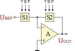
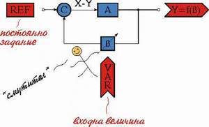 loop. Formulating a common rule for putting disturbances into the feedback loop.
8.5. Modification the circuit attributes by negative feedback.
8.5.1. Virtually increasing a resistance and decreasing a capacitance by series NFB. Deriving the idea of bootstrapping from many situations. Application 1: ramp generator - building the circuit from an external square generator, passive RC integrator, emitter follower and voltage "shifting" element. Application 2: Widlar current source. Discussion: Is it a circuit with feedback?
Last updated
August 13, 2005
1 2 3 4 5 6 7 8 9 10 11
home - bg - intro - contents - library - resources - feedback - digital