home - list of papers - short
![]() Third International Conference - Computer Science'06, Istanbul, Turkey, 12 - 15 October, 2006
Third International Conference - Computer Science'06, Istanbul, Turkey, 12 - 15 October, 2006
Cyril Svetoslavov Mechkov
Department of Computer Systems, Technical University of Sofia,
e-mail: cyril@circuit-fantasia.com, site: http://www.circuit-fantasia.com

Abstract: In this paper, a new educational approach for teaching negative resistance phenomenon is proposed. In opposite to the traditional approach, it relies mainly on human imagination and intuition. In the material proposed, negative resistance circuits are not analyzed as ready-made circuit solution by using formal explanations and definitions. Instead, first basic ideas behind these kinds of circuits are revealed. Then, basic procedures for building true negative resistors are derived. Finally, a set of real op-amp circuits with negative resistance (negative impedance converters) are built.
Keywords: negative resistance, negative differential resistance, negative resistors.
Color key: this page, other my pages, external, multimedia, handmade, analogies.
 1. INTRODUCTION. Negative resistance is one of the most interesting, strange and even mysterious circuit phenomena. Negative resistors and their most popular circuit implementations - negative impedance converters (NIC) - are real nightmare for students and their teachers because they are explained by formal means, which do not reveal the nature of the phenomena. Reading these resources, students will know what negative resistance is (for example, "a situation when current is a decreasing function of voltage"), but they will not really understand it. There is a need of "human-friendly" explanations of these legendary circuits. For this purpose, the following goals are posed in this work:
• to reveal the basic idea behind negative resistance phenomenon by using a set of heuristic means,
• to show how to obtain negative resistance,
• to establish a universal procedure for building various electronic circuits with negative resistance.
2. REVEALING THE BASIC IDEA BEHIND NEGATIVE RESISTANCE.
As human beings (not computers), we need something more than scientific facts, reports, formal explanations and definitions. In order to really comprehend the phenomenon of negative resistance (and of every new thing in this life), we need first to know what the general idea behind it is. Only, basic circuit ideas are in fact "non-electrical". They do not depend on the specific implementation (tube, transistor, op-amp etc.); they are eternal. So, we may find them in our routine.
2.1. Extracting the general idea from our routine.
We may observe this phenomenon in situations where someone (something) interferes to some extent in our life [1, 2 ]. He/she/it may help or impede us in three degrees (under-, exactly- or over-). Negative resistance represents the last degree when someone "over-helps" or "over-impedes" us. Examples: parents over-help children doing their work as with a magic wand, the excellent husband refunds the whole sum that his wife has spent and even adds additional money:), the pneumatic amplifier over-helps the driver so much that he has only to try pressing the pedal and it moves itself etc.
| A negative resistance phenomenon is a process of injecting an additional excessive power to an existing power source; a negative resistor acts as an additional power source. |
2.2. Comparison between "ordinary" and negative resistance. Now, let us move to the electrical domain and first answer the main question: What is negative resistance (resistor) versus ordinary resistance (resistor)?
2.2.1. A voltage source acting as a negative resistor. In order to compare an ordinary "positive" resistor R 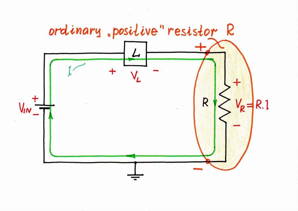
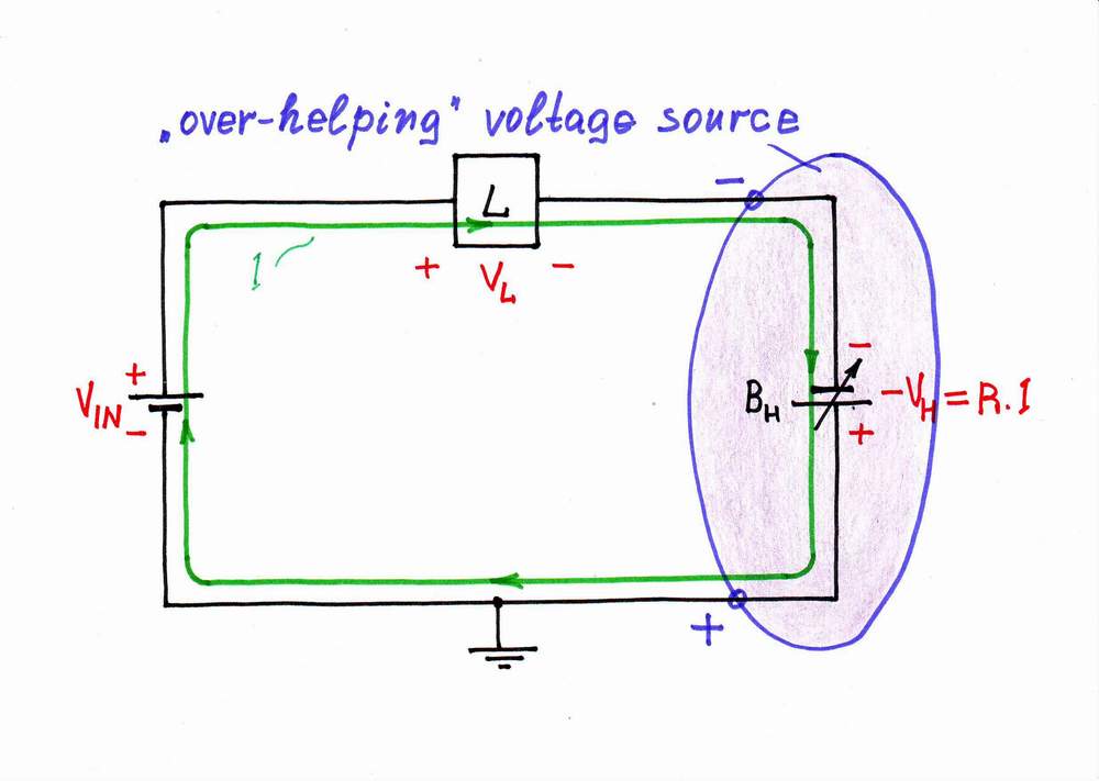 with a negative resistor -R, let us assemble two circuits where these components are connected in series with the loads so that the same current passes through them. As a result, a voltage drop VR = R.I appears across the "positive" resistor R (left) and the same voltage VH = VR = R.I appears across the negative resistor -R (right). Only, the resistor R sucks the voltage V = R.I from the circuit (it is a voltage drop) while the negative resistor -R adds the voltage V = R.I into the circuit. So, a resistor acts as a current-to-voltage drop converter while a negative resistor acts as a current-to-voltage converter. The element named "resistor" is really a resistor while here the "negative resistor" is actually a voltage source, whose voltage is proportional to the current passing through it. Now, we can answer the main question "What is negative resistor?"; the answer is simple and clear: A negative resistor is just a voltage source, whose voltage is proportional to the current passing through it.
If we connect the additional voltage source in the opposite direction versus the input voltage source, it will act as an "over-impeding" voltage source.
2.2.2. A current source acting as a negative resistor. Now, let us assemble the dual circuits where the components are connected in parallel to the loads so that the same voltage is applied across them. As a 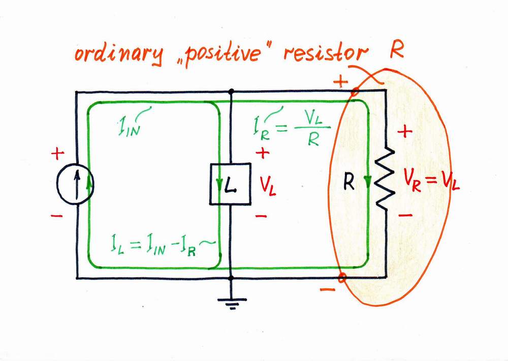
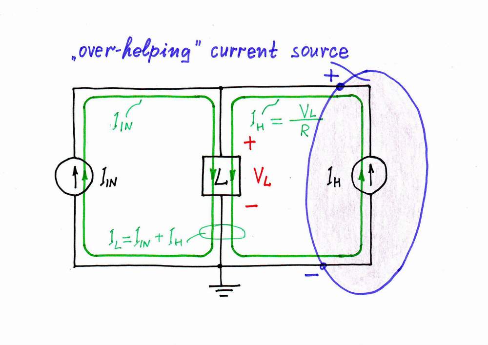 result, a current IR = VL/R passes through the resistor R (the left picture) and the same current IH = VL/R passes through the negative resistor -R (the right picture). Only, the resistor R sucks the current from the circuit while the negative resistor -R injects the current into the circuit. The element named "resistor" is really a resistor while here the "negative resistor" is actually a current source, whose current is proportional to the voltage across it. Thus, we have found another answer to the main question "What is negative resistor?": A negative resistor may be also a current source, whose current is proportional to the voltage across it.
If we connect the additional current source in the opposite direction versus the input current source, it will act as an "over-impeding" current source.
3. HOW TO MAKE NEGATIVE RESISTORS.
Once we have revealed the secret of negative resistance, we can already create a negative resistor.
 3.1. "Natural" negative differential resistors... In electronics, there are mysterious two-terminal electronic components having the so-called negative differential resistance. Some of them (e.g. neon lamps, thyristors) have an S-shaped IV curve while other components
(e.g. tunnel and Gunn diodes) have an N-shaped IV curve.
3.1. "Natural" negative differential resistors... In electronics, there are mysterious two-terminal electronic components having the so-called negative differential resistance. Some of them (e.g. neon lamps, thyristors) have an S-shaped IV curve while other components
(e.g. tunnel and Gunn diodes) have an N-shaped IV curve.
A chain of questions arise here: What is negative differential resistor? How does it actually work? What does it actually do in the region of negative differential resistance? We may find answers to these questions, if we place ourselves in the place of these strange components and begin performing their functions.
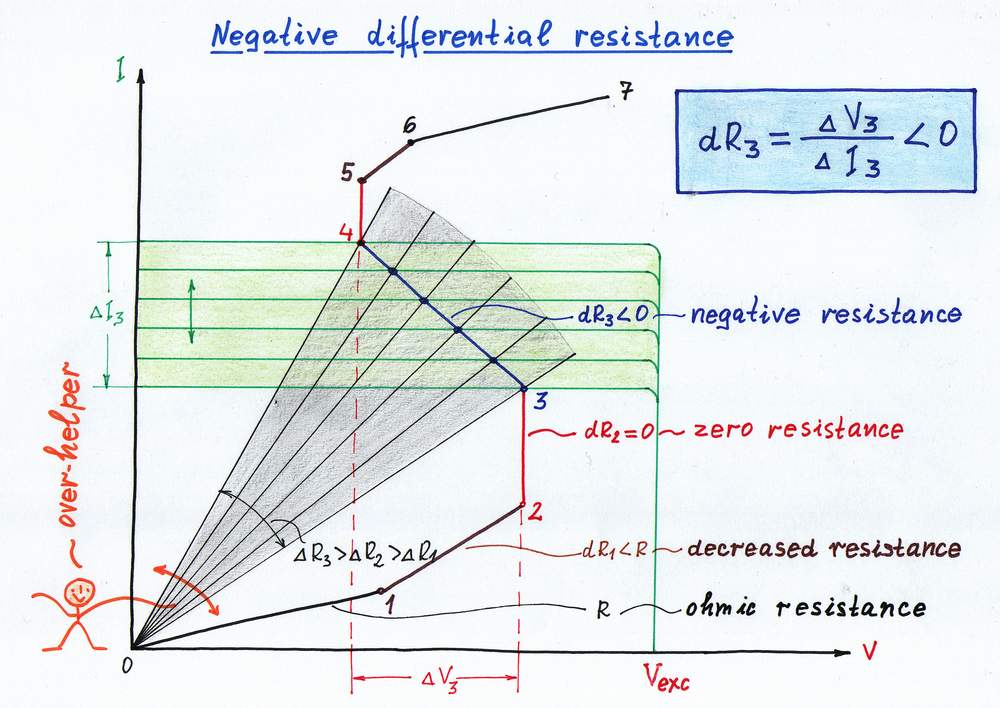
3.1.1. ...based on constant-voltage dynamic resistors (the left picture above). We may obtain them, if we begin dynamically decreasing the resistance of an ordinary ohmic resistor. First, we decrease gradually the ohmic resistance R (section 1-2) thus getting decreased differential resistance. Then, we decrease considerably enough the ohmic resistance (section 2-3), in order to get zero differential resistance (a voltage-stable dynamic resistor, a voltage stabilizer). Finally, decreasing enormously the ohmic resistance (section 3-4), we go so far that the IV curve folds; as a result, we obtain the desired S-negative differential resistance. In this way, following the sequence: ohmic > decreased > zero > S-negative differential resistance, we come to conclusion: An S-shaped negative differential resistor is actually an "over-acting" voltage-stable dynamic resistor.
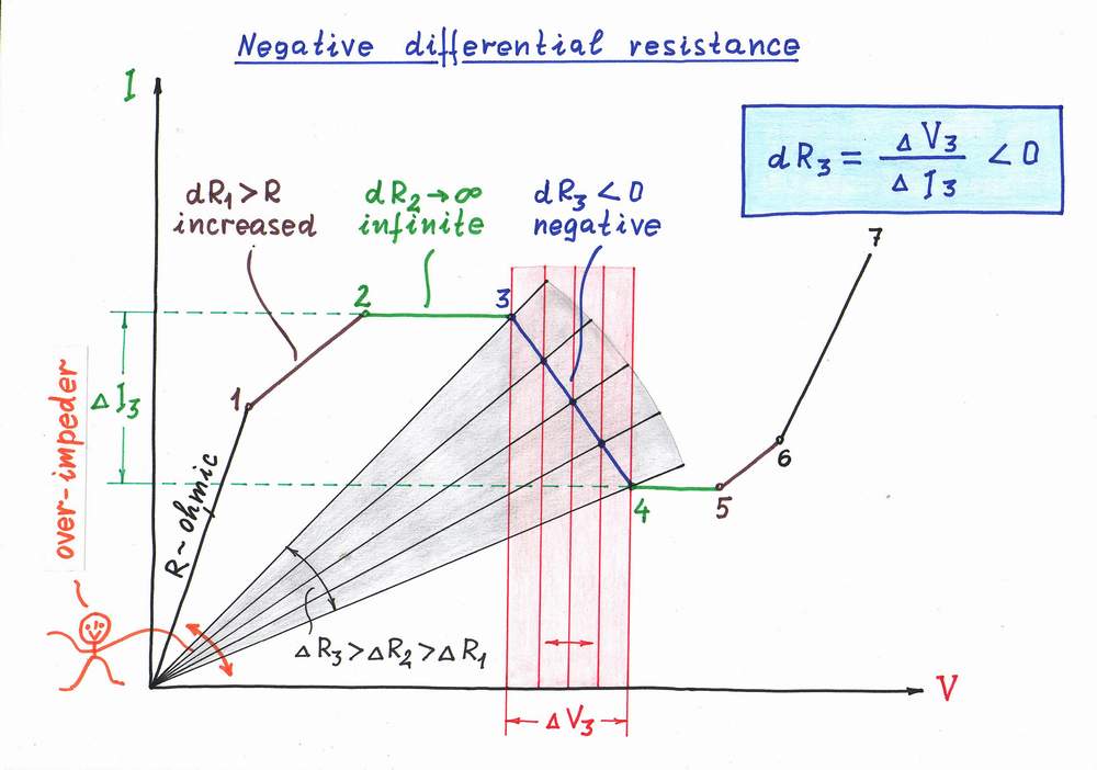
3.1.2. ...based on constant-current dynamic resistors (the right picture above). Similarly, we may obtain the dual negative resistors, if we begin dynamically increasing the resistance of an ordinary ohmic resistor. First, we increase gradually the ohmic resistance R (section 1-2) thus getting increased differential resistance. Then, we increase considerably enough the ohmic resistance (section 2-3), in order to get infinite differential resistance (a current-stable dynamic resistor, a current stabilizer). Finally, increasing enormously the ohmic resistance (section 3-4), we go so far that the IV curve folds; as a result, we obtain the desired N-negative differential resistance. In this way, following the sequence: ohmic > increased > infinite > N-negative differential resistance, we come to conclusion: An N-negative differential resistor is actually an "over-acting" current-stable dynamic resistor.
| Negative differential resistor acts as a dynamic resistor with considerably varying resistance. |
3.2. True negative resistors based on negative differential resistor. Only, the negative differential resistor that we have obtained is not a true negative resistor as it does not contain a source; it is just a part of a true negative resistor. In order to get completely true negative resistor, we have to connect in series an additional constant voltage source:
Negative differential resistor + constant voltage source = true negative resistor
An example: A negative resistance (tunnel diode) amplifier. Obviously, a true negative resistor can act as an amplifier. For this purpose, let us connect in series an input voltage source, a constant-voltage power supply, a "positive" resistor and a negative differential resistor (e.g., a tunnel diode). When the input voltage varies slightly, the negative differential resistor changes considerably its resistance according to the input voltage; so, the voltage divider changes noticeably its ratio. As a result, the voltage drops across the "positive" and negative resistors vary considerably; so, we may use some of them as an output voltage. In this arrangement, the differential negative resistor is not an amplifier; it is just a part of an amplifier (the differential negative resistor is just a 2-terminal regulating element). The combination of the differential negative resistor acting as a regulating element and the power supply constitutes an amplifier:
Negative differential resistor + power supply = negative resistance amplifier
3.3. True negative resistors based on a varying voltage source... In op-amp circuitry, we prefer to make dynamic resistors rather by varying the voltage than by varying the resistance. Following this approach, we can make "circuit" true negative resistors by connecting in series a "positive" (ohmic) resistor and an "over-acting" voltage-controlled voltage source (an amplifier):
"Positive" resistor + "over-acting" varying voltage source = true negative resistor
It seems quite strange that a "circuit" true negative resistor -R contains a "positive" resistor R. Only, we may see this idea in many cases of our routine where, in order to begin creating something positive (-R), we first need something negative (R). Then, we produce two (or many) times more positive quantity (-2R) in order not only to compensate the negative quantity (R) but also to get the desired positive quantity (-R = -2R + R). There are a few funny examples of this worldly phenomenon in 1, 2, 3.
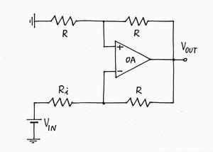
According to this idea, the "positive" resistor R converts the current into proportional voltage drop VR = R.I (see the left picture below); then, the "over-acting" varying voltage source VH (the amplifier) doubles this voltage drop thus producing an additional voltage VH = 2R.I. Half the voltage (VR) compensates the voltage drop VR; the rest half (VR) adds to the voltage of the excitation input voltage source VIN. As a result, the "positive" resistance R is converted into negative one -R. That is why, these kinds of circuits are named [4] negative impedance converters (NIC).
| A "circuit" true negative resistor -R contains an internal resistor R and a doubling voltage amplifier (K = 2). |
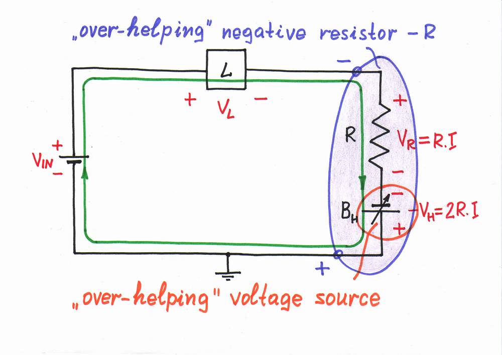 3.3.1. ...with "over-helping" voltage source. First, let us connect the additional voltage source so that it adds its voltage to the voltage of the input voltage source VIN (traversing the circuit clockwise the signs are - VIN +, - VH +). In this way, VH "over-helps" VIN since its voltage is two times more than the voltage drop VR. As a result, it reverses the voltage over the resistor R while the current continues flowing in the same direction.
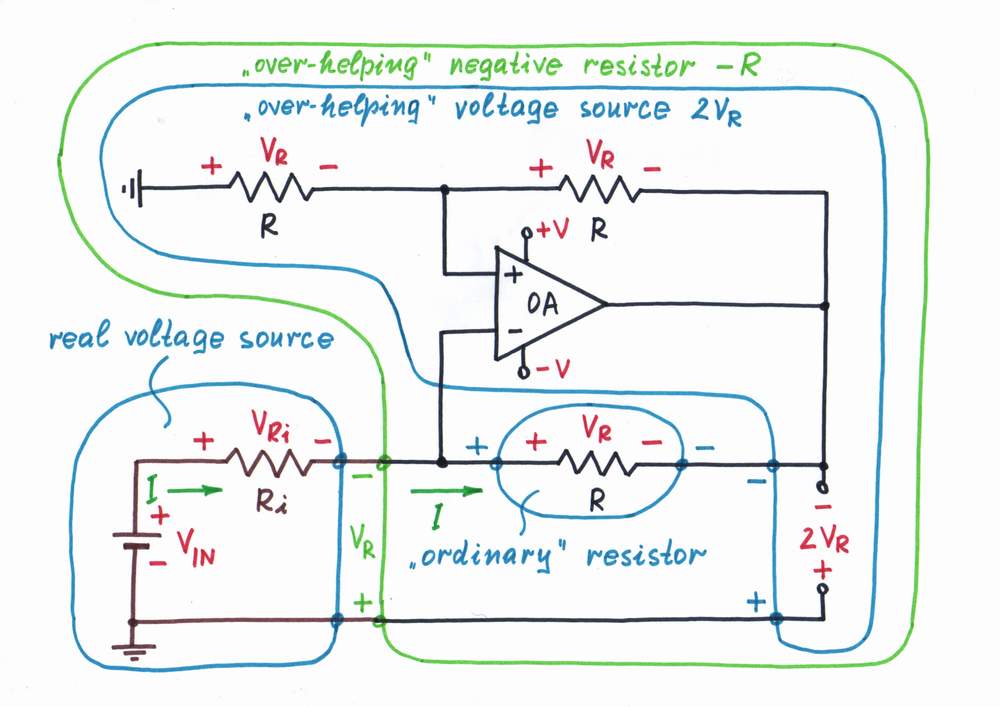 In order to put this idea in practice, we may connect in series to the resistor R the output part of an op-amp amplifier, which doubles the voltage drop across the resistor. All the op-amp inverting circuits (op-amp ammeter, transimpedance amplifier, op-amp integrator, op-amp inverting current source etc.) exploit this idea. Only, in these circuits the op-amp acts as an additional "helping" voltage source, which compensates "exactly" the voltage drop across the resistor R2. Maybe, the most suitable example of this trick is transimpedance amplifier. Actually, the main task of the op-amp in this circuit is to remove (zero) the resistance R. In order to convert this "positive" circuit into negative one, we have just to "mislead" the op-amp making it "over-act". If we connect a voltage divider (with K = 0.5) to the non-inverting input, we will make the op-amp "over-compensate" twice the voltage drop VR; thus we will get a negative resistance -R.
This circuit is referred to as current-inverting negative impedance converter (INIC). There is a dual voltage-inverting negative impedance converter (VNIC. Only, if we consider these 2-port circuits as 1-port negative resistors, they are the same devices.
An operation. The op-amp continuously compares 1/2 of its own output voltage VOA with the voltage drop VR across the resistor R by subtracting the two voltages. It "observes" the result of the comparison - the voltage difference between the two inputs and keeps it almost zero by adjusting the output voltage VOA. The op-amp is "misled" - it has to generate two times higher voltage VOA = -2VR = -2R.I, in order to keep zero voltage between its two inputs. Half the voltage (-VR) compensates the voltage drop VR; the rest half (-VR) is added to the excitation voltage source VIN. The resistance of NIC is RNIC = (-V)/I = -R.
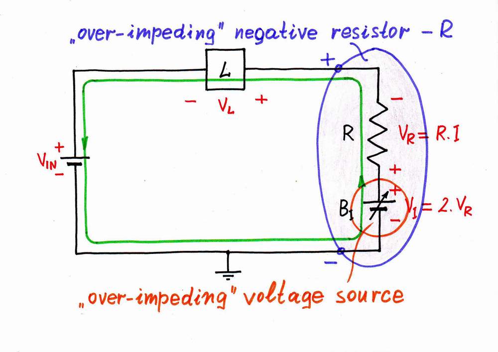 3.3.2. ...with "over-impeding" voltage source. If we reverse the additional voltage source, it will subtract its voltage from the voltage of the input voltage source VIN (traversing the circuit again clockwise the signs are - VIN +, + VI -); now, VI will "over-impede" VIN. As a result, it reverses the current passing through the resistor R while the voltage across the new "resistor" -R keeps the old polarity.
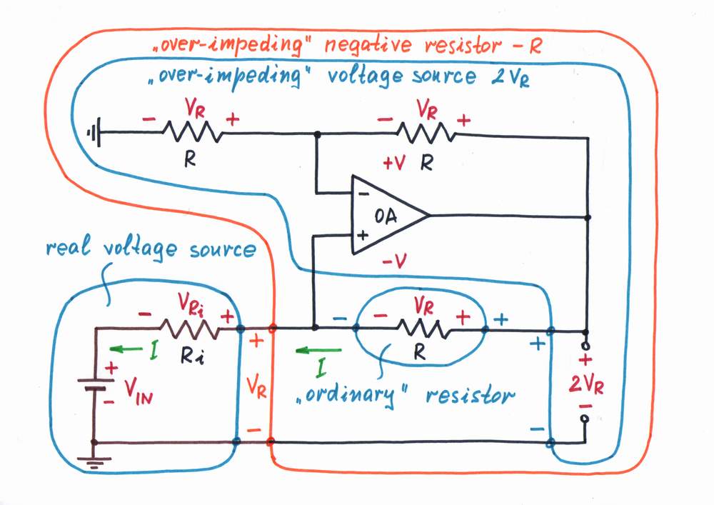 In this case, we have again to make the op-amp produce two times higher voltage than the voltage drop VR. Only, it has now to act as an "over-impeding" voltage source. Again, if we connect a voltage divider with K = 0.5 between the op-amp output and the inverting input, we will make the op-amp to "over-act". Actually, we have obtained the classical circuit of an op-amp non-inverting amplifier with K = 2.
An operation. As above, the op-amp continuously compares 1/2 of its own output voltage VOA with the voltage drop VR across the resistor R by subtracting the two voltages. As usual, it "observes" the result of the comparison - the voltage difference between the two inputs and keeps it almost zero by adjusting the output voltage VOA. Again, the op-amp is "misled" - it has to generate two times higher voltage VOA = 2VR = 2R.I, in order to keep zero voltage between its two inputs. Actually, it doubles the voltage VR appearing at the left side of the "ordinary" resistor R and applies it to its right side. Half the voltage (VR) compensates the voltage drop VR; the rest half (VR) is subtracted from the excitation voltage source VIN. As a result, the current I reverses its direction - now it flows into the input voltage source. The resistance of NIC is again RNIC = V/(-I) = -R.
4. CONCLUSIONS. Applying the heuristic approach in this paper,
• first, we have revealed the basic idea behind negative resistance circuits,
• then, we have derived a few procedures for building true negative resistors,
• finally, we have built a set of real op-amp circuits having negative resistance.
5. REFERENCES.
Circuit stories: How do we create dynamic resistance? How do we make decreased, zero and negative differential resistance?
How do we make decreased, zero and negative resistance? What is the idea behind NIC?
Transimpedance amplifier (current-to-voltage converter), How do we invent constant current source?
Wikipedia articles: Negative resistance, Transimpedance_amplifier
Wikipedia discussions: Another fresh viewpoint at negative resistance, What is the basic idea behind negative impedance converter (NIC)?
Other web resources: Negative Resistance Circuits, The mysterious "negistor"
home - list of papers - short
Last updated, December 15, 2006